
Add to Cart
This WiFi module has UART interface. And it is more powerful, with
more functions
Summary
TLG10UA03 is a new embedded Uart-Wifi modules.
Uart-Wif is an embedded module based on the Uart serial,according
with the WiFi wireless WLAN standards, It accords with IEEE802.11
protocol stack and TCP / IP protocol stack,and it enables the data
conversion between the user serial and the wireless network module.
through the Uart-Wifi module, the traditional serial devices can
easily access to the wireless network.
TLG10UA03 does a comprehensive hardware and software upgrades based
on the products of the first two generations, now it’s more
functional and more convenient to use,its main features include:
1,Support transparent transmission of serial completely,and achieve
a plug and play serial
2,Support new AT+instruction set, Which is all based on ASCII
format, it’s simple to use and pellucid.
3,Support more perfect TCP/IP protocol tack, support DHCP protocol
for dynamicassignation of IP address and DNS domain name parsing.
4,Embed WEB server, and achieve the long-range parameters
configuration through wireless network with IE browser.
5,Support more prefect transmission performance,the maximum sending
rate can reach to 11KB/s.
Characteristic
1)Interface
2*4 pins of Interface: HDR254M-2X4
The range of baud rate: 1200~ 115200bps
RTS/CTS Hardware flow control
Single 3.3V power supply
2)Wireless
Support IEEE802.11b/g wireless standards
Support the range of frequency: 2.412~2.484 GHz
Support two types of wireless networks: Ad hoc and Infrastructure
Support multiple security authentication mechanisms:
WEP64/WEP128/TKIP/CCMP(AES)WEP/WPA-PSK/WPA2-PSK
Support quick networking
Support wireless roam
3)Others
Support multiple network protocols : TCP/UDP/ICMP/DHCP/DNS/HTTP
Support two types of work modes: auto and command
Support transparent transmission mode
Support AT+ instruction set
Support a variety of parameters configuration methods: serial/WEB
server/wireless connection
4)Application
Intelligent bus network, such as wireless credit card machine
Small financial payment network, such as wireless POS machine
Industrial equipment networking, such as wireless sensor things
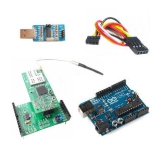
Test
Here we supply a detailed test example. You can download the test
file in the Download list. With Arduino WiFi Module Shield, this
wifi module can easily compatable with Arduino.
First you should configure the wifi module. On your PC you should
visit the admin panel of your wifi network. Usually this address is
http://192.168.1.1
Connect wifi module with PC via USB-TTL module. Start wifi software
to find the device. Input all the information needed to configure
the wifi module.
Set the wifi IP address 192.168.1.119 in server mode. Port is 8089.
After the configuration on wifi module, upload the following code
to Arduino:
void setup()
{
Serial.begin(115200);
}
void loop()
{
boolean currentLineIsBlank = true;
while(1){
if (Serial.available()) {
char c = Serial.read();
// if you've gotten to the end of the line (received a newline
// character) and the line is blank, the http request has ended,
// so you can send a reply
if (c == 'n' && currentLineIsBlank) {
// send the webpage
Serial.println("HTTP/1.1 200 OKrnContent-Type:
text/htmlrnrn<center><h1>Hello World!! I am WiFi
WebServer!!!</h1></center>");
break;
}
if (c == 'n') {
// you're starting a new line
currentLineIsBlank = true;
}
else if (c != 'r') {
// you've gotten a character on the current line
currentLineIsBlank = false;
}
}
}
}
Connect WiFi module with Arduino
In your browser, visit http://192.168.1.119:8089
Finally here comes the WiFi shield for Arduino. We have UART WiFi
Network Server/Client Module Kits. However, you have to connect
wires by hand to Arduino. Now, with this module, you can get rid of
the wires from your Arduino. Just plug in and play.
Interface
Besides the interface for wifi module, this shield has some other
interface on it.
Port 2: Here we use special designs to allow your wifi module
switch communication with between Arduino or your PC. We made a
mark to indication the plugging. In the picture above, wifi module
can communication with Arduino.
Port 3: UART interface, considering this shield would be used in
other cases, we extended UART interface from Arduino. The 4 pins
above are: 3.3V, TX, RX, GND. The 4 pins below are 5V, TX, RX, GND.
All the TX and RX are 5V TTL. But 5V TTL and 3.3V TTL are
compatible. please note port 2 could determin the TX and RX pins.
As the port 2 setting above in the picture, the pins of port 3 will
be as the mark on the board. You can refer to the design document
for more information
Port 4: I2C port of Arduino.
Port 5: The pins are 5V, digital pin7 on Arduino, digital pin6 on
Arduino, GND. We place this port on board because some times we
need to use soft-serial or soft-I2C to communicate.
If you want to know more information about this kit, please
download and see the configuration step by step in the test file.
You can download below.
Document Download

