
Add to Cart
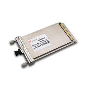
100G CFP LR4 Compatible 100GBASE-LR4 1310nm 10km Transceiver Module
Fiberroad 100G CFP LR4 is a optical transceiver module which is a hot pluggable form factor designed for high speed optical networking application. It is designed for 100 Gigabit Ethernet application and provides 100GBASE-LR4 compliant optical interface, CAUI electrical interface and MDIO module management interface.
The 100G CFP LR4 converts 10-lane 10.3Gb/s electrical data streams to 4-lane LAN-WDM 25.78Gb/s optical output signal and 4-lane LAN-WDM 25.78Gb/s optical input signal to 10-lane 10.3Gb/s electrical data streams. This 10-lane 10.3Gb/s electrical signal is fully compliant with IEEE 802.3ba CAUI specification. The high performance Cooled LAN-WDM EA-DFB transmitter and high sensitivity PIN receiver provide superior performance for 100Gigabit Ethernet applications up to 10km links and compliant optical interface with IEEE802.3ba 100GBASE-LR4 requirements. The 100G CFP LR4 contains a duplex LC connector for the optical interface and a 148-pin connector for the electrical interface, the functional block diagram shown as below.
Features
Compliant to CFP MSA Management Interface Specification
Applications
Transmitter
The transceiver module receives 10-lane 10.3 Gb/s CAUI electrical inputs. The gearbox multiplexes 10-lane electrical signals to 4-lane electrical signals. The multiplexed 4-lane signals are fed to the transmitters. The four transmitters convert 4-lane signals to an optical signal through 4 Laser drivers and Lasers diodes which are packaged in the Transmitter Optical Sub-Assembly (TOSA). Each Laser launches optical signal in specific wavelength specified in IEEE802.3ba 100GBASE-LR4 requirements. These 4-lane optical signals will be optically multiplexed into one fiber by 4 to1 Optical WDM MUX which is in the TOSA. The optical output power is held constant by an automatic power control (APC) circuit. The transmitters output can be turned off by TX_DIS hardware signal and/or through MDIO module management Interface.
Receiver
The Fiberroad CFP LR4 receives 4-lane LAN WDM optical signals. The optical signals are de-multiplexed by 1 to 4 optical DE-MUX and fed into each Receiver Optical Sub-Assembly(ROSA)integrated 1:4 optical DE-MUX. The ROSA converts optical signal to electrical signal. The 4-lane regenerated electrical signals are de-multiplex to 10-lane signals by the 4 to 10 gearbox. The 10-lane signals are compliant with IEEE CAUI interface requirements. Each received optical signal is monitored by the DOM section. The monitored value is reported through the MDIO section. If one or more received optical signal is weaker than the threshold level, RX_LOS hardware alarm will be launched.
Dimensions
Optical Transmitter Characteristics
| Parameter | Symbol | Min | Typ. | Max | Unit | Notes |
| Signaling rate, each lane | 25.78125 | GBd | ||||
| Lane wavelength(range) | 1294.53 | 1295.56 | 1296.59 | nm | ||
| 1299.02 | 1300.05 | 1301.09 | nm | |||
| 1303.54 | 1304.58 | 1305.63 | nm | |||
| 1308.09 | 1309.14 | 1310.19 | nm | |||
| Rate tolerance | -100 | 100 | ppm | From nominal rate | ||
| Side-mode suppression ratio | SMSR | 30 | dB | |||
| Total launch power | 10.5 | dBm | ||||
| Average launch power, each lane | Pavg | -4.3 | 4.5 | dBm | ||
| Extinction Ratio | ER | 4 | 8.2 | dB | ||
Optical modulation amplitude, each lane (OMA) | OMA | -1.3 | 4.5 | dBm | ||
Difference in launch power between any two lanes (OMA) | 5 | dB | ||||
Transmitter and Dispersion Penalty, each lane | TDP | 2.2 | dB | |||
| OMA minus TDP, each lane | OMA-TDP | -2.3 | dBm | |||
Average launch power of OFF transmitter, each lane | -30 | dBm | ||||
| Relative Intensity Noise | RIN20O MA | -130 | dB/Hz | |||
| Transmitter reflectance | -12 | dB | ||||
Transmitter eye mask {X1, X2, X3, Y1, Y2, Y3} | {0.25, 0.4, 0.45, 0.25, 0.28, 0.4} | |||||
Optical Receiver Characteristics
| Parameter | Symbol | Min | Typ. | Max | Unit | Notes |
| Signaling rate, each lane | 25.78125 | GBd | ||||
| Rate tolerance | -100 | 100 | ppm | From normal rate | ||
| Average receive power, each lane | Pavg | -10.6 | 4.5 | dBm | ||
| Receive power, each lane (OMA) | 4.5 | dBm | ||||
Difference in receiver power between any two lanes (OMA) | 5.5 | dB | ||||
Receiver Sensitivity (OMA), each lane | Rsen | -8.6 | dBm | 1 | ||
Stressed Receiver Sensitivity (OMA), each lane | SRS | -6.8 | dBm | |||
| Stressed receiver sensitivity test conditions | ||||||
| Vertical eye closure penalty, each lane | VECP | 1.8 | dB | |||
| Stressed sys J2 jitter, each lane | J2 | 0.3 | UI | 2 | ||
| Stressed sys J9 jitter, each lane | J9 | 0.47 | UI | 2 | ||
| Receiver reflectance | -26 | dB | ||||
| LOS Assert | Plos_on | -18 | dBm | |||
| LOS Deassert | Plos_off | -15 | dBm | |||
| LOS Hysteresis | 0.5 | dB | ||||
| ||||||

