
Add to Cart
One year free update online!
Honda car model updated to 2011.12, Kia updated to 2011.06!
Attention: Autel company cancel Holden this car model, so DS708 do
not contain holden.
Description:
MaxiDAS® DS708 is a state-of-art diagnostic system that delivers
more accurate, more stable, more comprehensive, easier and faster
diagnosis. The new generation platform stands out in a variety of
tools by providing incredibly high performance with intuitive
operation. Right for the first time, workshops and technicians
could find an OE-level diagnostic solution designed for the
aftermarket. The DS708 is the key to gain customer confidence and
boost your bottom-line.
New DS708 package cancel USB cable, please pay attention.
Feature and Function:
1.Extensive vehicle coverage for more than 30 domestic, Asian and
European vehicle makes
2.Deep vehicle system coverage for ALL electronic systems
3.Complete function capability including live data, ECU programming
and so many others
4.Unparalleled OBDII functionalities supports ALL 5 OBDII protocols
and ALL 9 test modes
5.Automatic Wi-Fi updates available in new software releases
6.Innovative dual-processor technology for quicker diagnostics and
boot-up
7.The genuine Windows CE operating system allows for more stable
performances, better compatibility and expandability
8.Internet explorer brings internet resource of your choice at your
fingertips
9.WIFI internet capability allows for wireless access throughout
the workshop
10.Advanced USB communication for faster operation and more
accurate diagnostics
11.Extremely easy-to-us with touch-screen operation and intuitive
operation
12.Unique shop tough ergonomic design features multi-layered rubber
protection and strong housing
13.Intelligent memory of vehicles for easy and quick diagnosis of
tested vehicles
14.Captures, saves and prints screenshots for convenient
troubleshooting
15.Displays live data in text, graph and analog for easy data
review and analysis
16.Records and playbacks live data to pinpoint troubles of sensors
and components
17.Innovative graph merging for easy and quick detection of
intermittent problems
18.Automatic WIFI Data Logging for quick and accurate technical
support and troubleshooting
19.Built-in overvoltage protection keeps the instrument and vehicle
from unwanted damages
20.Creative remote diagnosis for convenient demonstrationand
training
21.Powered by Autel® Uni-SCANTM technology with no need for extra
adaptors or "keys"
22.Prints out recorded data any time and anywhere with Wi-Fi
printing capability
Specifications
Operating System: Windows CE
CPU: ARM9+ARM7 dual processor
Memory: Max. 4 Gigabyte SD card
Communication Interface: OBD,USB Ethernet
Input Voltage: 8.0-32.0V power provided via vehicle battery
Power Consumption: 8W
Operating Current: 500mA
Display: Backlit, 7" TFT (800*480 dpi) color display with
touchscreen
Operating Temperature: 0 to 60°C
Storage Temperature: -10 to 70°C
Operation: Touchscreen and one rubber key (ON/OFF)
Printer Interface: Wi-Fi, USB, Ethernet
Housing: Strong plastic housing with protective rubber boot
Protocols: ISO 9141-2, K/L lins, flashing code, SAE-J1850 VPW,
SAE-J1850 PWM, CAN ISO 11898
ISO15765-4, High-speed, Middle-speed, Low-speed and Single-wire CAN
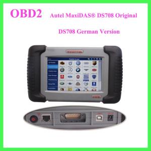
Component Descriptions
1. Main Connection Port Connect to the mains for power supply of
updating, printing data logging and internet access after
disconnecting from the vehicle.
2. USB Connection Port Connect to the computer for updating and
printing.
3. Diagnostic Socket Provides power supply and connection to the
vehicle via diagnostic cables and connectors supplied.
4. Internet Connection Port Provides internet access for updating,
printing and data logging and brings the internet resource of your
choice at your fingertips.
5. ON/ OFF Button Powers on/ off the diagnostic tool.
Note: The scan tool will not turn off automatically; it stays on
until you turn it off.
6. LED Indicators
The three light-emitting diodes indicate certain system conditions,
Communication LED – Green LED light in middle shows when the unit
is in service.
Wireless LAN activity LED – Green LED light in the left shows when
a wireless local area network in enabled, flashes when data is
being sent or received.
Main Power LED – Red LED light in the right shows when the unit is
powered on.
7. SD Card Slot
The standard SD (Secure Digital) card slot enables the unit to read
and write data to the card inserted in the slot. To use the
software, insert the card with the metal contacts facing down and
pointing toward the MaxiDAS.
Note: Do not force media into the SD card slot. This may damage the
SD card slot. To Remove SD Card, press the card again and slot will
pop out card automatically.
Software Descriptions
This section shows the software which is currently used for the
tool.
The MaxiDAS software is provided on a SD Memory card and can be
updated. Free
software updates are available periodically on the Internet at www.
maxidas.com.
1. Software Applications Overview
The software has two main features: perform vehicle component test
and provide information that may assist you in understanding the
component.
Scan Diagnostic Applications
To perform scan diagnostic tests, identify a vehicle you wish to
test from the main screen.
Following the instruction on each screen that appear to access to
the function test. The
diagnostic functions varies depend on the type of vehicle.
Auto Scan (HONDA) … Chapter 5
Diagnostic Trouble Codes…Chapter6
Live Data (OBDII) …Chapter 7
Freeze Frame …Chapter 8
Component Test(OBDII Only) … Chapter 9
I/M Readiness (OBDII Only)… Chapter10
O2 Mon. Test ( O2 Monitor Test)( OBDII Only)…Chapter11
On-Board Mon. Test (OBDII Only) …Chapter 12
Playback
The Playback function is used for reviewing saved data files. The
data files are saved to the Maxidas’s memory card with the data
stream saving function, DTC saving function,freeze frame saving
function and the automated testing and diagnostic system. See
Chapter … at Page …for details
Update
Setup
WIFI
Network
Unit
Date/Time
Language
Backlight
Beep
Touch
Remote desk
About
8. Stylus The Stylus is used for typing and selecting. To
calibrating Touch Screen, refer to chapter 7 – 8, Calibrating Touch
Screen.
9. Stand The built- in metal stand allows the unit to rest for
hands-free viewing when extended. It is attached to the back of the
scan tool and can be secured to the back again unit when not in
use.
10. Handgrip The handgrips are attached to both sides of the
MaxiDAS unit. Hold the handgrips to stabilize the unit while using.
The handgrip also eliminates the damage when you drop the tool
accidentally.
11. MaxiDAS 708 Label
The Label includes the notice and warning.
12. LCD Screen Displays the menus and data screens.
Important: Use the supplied stylus or plastic-tipped pens for touch
screen display. Do not use pencil, pen or any sharp object on touch
screen display.
13. Memory Card
The Memory Card contains the tool’s diagnostic software,
applications and maximum of 4 Gigabytes storage.
Note: Do not remove the memory card while the unit is in service.
14. DLC Cables
The DLC (Data Link Connector) Cable is used to connect between the
scan tool and vehicle’s DLC. Numbers of cables are provided; select
the appropriate one for the vehicle being tested. An optional
extension cable may also be used.
15. AC Power Supply
The AC power supply and power cord (12V and 3.33A) is used to power
the scan tool from wall socket.

