
Add to Cart
Description
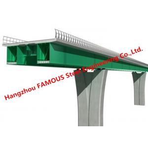
Steel Box Girder Bridge refers to a beam bridge whose main beam is in the form of a thin-wall closed section. Long hollow trusses made of steel or concrete are usually used as beams. This makes the bridge light and sturdy. Bridges constructed using this method are called Steel Box Girder Bridge.
Specification
| Product Name | Steel box girder bridge |
| Width | 4.2meter |
| Maximum span | 64meter single span |
| Bridge deck | Steel composit panel |
| Steel grade | Q345B |
| Loading capacity | 20ton, 40ton truck etc, or HS20-44, HS25-44/Truck 20 |
| Corrosion | Hot dip galvanized |
| Advantages | Price effective and technical full analysis and supports |
Steel box girder bridges are commonly used for highway flyovers and for modern elevated structures of light rail transport. Although normally the steel box girder bridge is a form of beam bridge, box girders may also be used on cable-stayed bridges and other forms.
Parts of the bridge
The basic Bailey bridge is made up of three main parts, the floor,
the stringers and the side panels. The floor of the bridge is made
up of a number of 19-foot-wide transoms (5.8 m) that run across the
bridge. Across the bottom of these, forming a square, are
10-foot-long stringers (3.0 m). The bridge's strength is provided
by the panels on the sides. The panels are 10-foot-long (3.0 m),
5-foot-high (1.5 m), cross-braced rectangles. Each weighs 570
pounds (260 kg), and can be lifted by six men.
Application
Generally used for urban bridges or highway viaducts and overpasses
with small spans
Reinforced concrete: medium and small span
Prestressed reinforced concrete: large span
Straight leg frame (door type) and slant leg frame: medium and
small span
T-shaped rigid frame, continuous rigid frame: large span
· Road Bridges
· Pedestrian Bridges
· Railway Bridges
· Steel Truss Bridge
· Beam Bridges
· Steel Bailey bridge
· Structural Steel Box Bridge
· Highway Bridges
· Composite Beam Bridge
· Cable-Stayed Bridge
· Floating Bridge etc.
Construction
For steel box girders, the girders are normally fabricated off site
and lifted into place by crane, with sections connected by bolting
or welding. If a composite concrete bridge deck is used, it is
often cast in-place using temporary falsework supported by the
steel girder.
Either form of bridge may also be installed using the technique of incremental launching. Under this method, gantry cranes are often used to place new segments onto the completed portions of the bridge until the bridge superstructure is completed.
Features
Modular, pre-engineered, pre-fabricated bridge system
Standard interchangeable components
Highly adaptable, fully reusable and re-locatable
Transported in standard ISO containers
Quick and simple to build using labour
Fully galvanized for long life and minimum maintenance
3.048m module length
4.2m single lane
Proprietary steel decking systems to suit different loading
requirements
Durbar finish or factory applied anti-skid surfacing
Full highway load carrying capability
Simple, cost effective foundations
Our company
Our experienced team is focused on your steel bridge project's success, from start to finish. Our proven ability to identify and overcome design inconsistencies, potential problems with erection, and shipping obstacles results in the fabrication of structural steel that is right the first time, helping you avoid costly construction delays.
Finally
The success of the Bailey bridge was due to the simplicity of the fabrication and assembly of its modular components, combined with the ability to erect and deploy sections with a minimum of assistance from heavy equipment. Many previous designs for military bridges required cranes to lift the pre-assembled bridge and lower it into place. The Bailey parts were made of standard steel alloys, and were simple enough that parts made at a number of different factories could be completely interchangeable. Each individual part could be carried by a small number of men, enabling army engineers to move more easily and more quickly than before, in preparing the way for troops and materiel advancing behind them. Finally, the modular design allowed engineers to build each bridge to be as long and as strong as needed, doubling or tripling up on the supportive side panels, or on the roadbed sections.