
Add to Cart
Quick details
– Rapid response protection for electrical machines
– Compact size for easy assembly into windings
– Silvered copper leads
Description
PTC thermistors act as thermal protectors for electrical motors. They are available with or without an insulated sleeve and have flexible connecting leads. PTC thermistors have a non-linear resistance/temperature response. At a specified temperature the resistance changes rapidly to a very high value.
Application
Motor Protection and Electronics.
Specification
| Dimensions (mm) | ||||||||||||||||||||||||||||||||||||||||||||
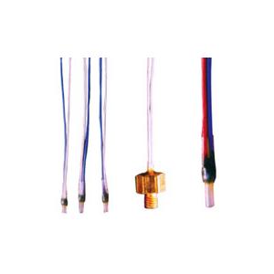
| CYGM1 Single Thermistor with shrunk-sleeve & epoxy seal
| ||||||||||||||||||||||||||||||||||||||||||||
CEF1
When ordering please specify thread size, otherwise the stock M4 size will be supplied. | ||||||||||||||||||||||||||||||||||||||||||||
CYGM3
| ||||||||||||||||||||||||||||||||||||||||||||
OPERATION
PTC thermistors exhibit very high sensitivity over a narrow temperature band. For temperature measuremen
in this range, NTC thermistors are easier to measure and more accurate.
PTC thermistors are especially suited as temperature sensors for monitoring the windings of electric machines, and also for use in simple fail-safe circuitry. When a given temperature (nominal response temperature qNAT) is exceeded, the circuit can be switched off through a relay or amplifier, since the PTC-sensor will have an extremely high ohmic value in the region of its response temperature. This will have the same effect as a break in the circuit or a failure of the thermistor.
TECHNICAL DATA 80° C to 180° C in steps of 10°, plus 145° and 155° T max. 200° C Umax 25V (per bead) 690 mW 2.5 kV
with teflon insulationPTFE approx 10 mm 0.25 mm 2 for single, double and triple PTC’s CONDUCTOR LENGTHS
Single PTC 500 mm 6 10 mm
Triple PTC 500 - 180 - 180 - 500 mm 6 10 mm
SPECIAL VERSIONS
PTC’s are also available in many special housings (can be manufactured to customers specifications)
INSTALLATION TIPS
For PTC temperature sensors in electrical windings:
- the thermistors can only be inserted in the windings before impregnation
- it is advisable to embed one in each phase, if possible in the centre of the coil generating most heat, and generally on the outflow side of any air movement
- air inflow onto the temperature sensor will interfere with heat transfer
- if using varnish/lacquer which is not chemically neutral, suitability tests must be undertaken by the customer
- WARNING! It is very important that the sensor must be installed parallel with the copper of the winding, so that the teflon leads can assume the form of the rest of the winding and thereby retain the highvoltage resistance rating.
- PTC’s are classified according to their nominal response temperature ϑNAT but all have similar resistance characteristics to simplify the choice of switching device; the relationship of resistance to temperature of all these PTC’s is as follows:STANDARD RESISTANCE VALUES
Single PTC
Triple PTC
* One PTC might reach ϑNAT + 15 °C, while the second or even both of the others could still remain at room temperature.
The PTC’s resistance values for motor protection are specified in DIN 44081/44082. Resistance values below ϑNAT –20 are not specified, and resistance when cold is no indication of the PTC’s condition. It is ideally between 40 - 200 ohms but can be anywhere between 35 - 250 ohms.
The greatest resistance change occurs between +/-5 °C either side of ϑNAT, being at least 15%/K.
QUALITY STANDARD
Random testing is carried out according to DGQ P90/P10 (DIN 40080). AQL values can be fixed by arrangement.
ORDERING INFORMATION
TEMPERATURE-RESISTANCE CURVE

