
Add to Cart
IEC60245-2 Cable Testing Equipment Static Flexibility Tester For Completed Flexible Cables
Structure introduction
The machine is composed of sliding clamp, fixed clamp, left and
right limit protection, screw drive structure and electric control
board.
1.The sliding clamp and the fixing clamp are mainly composed of a
clamp seat and a clamp block, and the handle bar is rotated to push
the clamp block to clamp the two ends of the sample respectively. Cable Testing Equipment
2.There is a limit switch on each of the left and right sides to
protect the sliding fixture to avoid collision.
3.The screw drive structure drives the sliding clamp to move left
and right.
4.The electric control board is a manual control panel with
switches such as left shift, stop, right shift, power supply and
speed control.
Standard:IEC60245-1 Rubber insulated cables-Rated voltages up to and including 450/750 V-Part 1:General requirements,IEC60245-2 clause 3.2 and Figure 2 Rubber insulated cables-Rated voltages up to and including 450/750 V-Part 2: Test methods. Cable Testing Equipment
Application:It is used for checking mechanical strength of completed flexible cables. This test does not apply to flexible cables with cores of nominal cross-sectional area greater than 4mm2 and cables having more than 18 cores laid up in more than two concentric layers.
Test sample:Completed flexible cables. Cable Testing Equipment
Feature:A sample with a length of 3m±0.05m shall be tested in an apparatus similar to that shown in figure 2. Two clamps, A and B, shall be located at a height of at least 1.5m above ground level. Clamp A shall be fixed and clamp B shall move horizontally at the level of clamp A. The ends of the sample shall clamped vertically (and remain vertical during the test), one end in clamp A, the other in the movable clamp B which shall be at a distance /=0.20m from clamp A. The cable takes roughly the shape indicated figure 2 by the dotted lines. The movable clamp B shall then be moved away from the fixed clamp A until the loop formed by the cable takes the shape, indicated in figure 2 by the heavy outline, of the U enclosed wholly between two plumb lines through the clamps and set up tangentially to the external generatrix of the cable. This test shall be done twice, the cable being turned in the clamp, after first test, through 180°. Cable Testing Equipment
Parameters:
| A, B clamping head initial distance | 200mm |
| A and B, shall be located at a height above ground level | At least 1.5m |
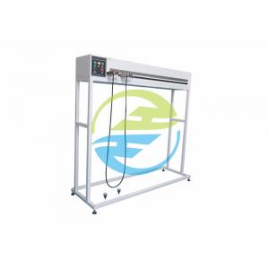
Picture for reference: