
Add to Cart
Custom Rogers,Taconic,Isola,F4B PCBs are our forte. We enjoy
working with clients who can give us a challenge. Our Rogers and
other high frequency PCBs can be created in many shapes and size.
We have the capabilities to create RF printed circuit boards with
large panel sizes up to 18" x 24".
We work alongside our clients to design every aspect of the PCB,not
only rogers,Taconic,F4B PCB board,we also supply FR408HR, 370HR,
and FR406 board.
The fabrication process is completed using a variety of high-end
technologies. Our fabrication methods include scoring and array
layouts among others. We utilize laser technology to accurately
complete our trimming, drilling, and routing processes.
We offer eclectic options for circuit board tracing, etching, and
soldering. We also offer silk screen printing in white, red, black,
and yellow.
| Product Name | Rogers3003 Gold Plating RF Circuit,Rogers PCB,Taconic PCB,F4B PCB,Isola PCB,etc |
| Material | Rogers,Taconic,Arlon,F4B etc. |
| Color | White,Black,Yellow,Red,Blue,Purple etc. |
| Standard | RoHS,CE,SGS |
| Surface treatment | OSP,Immersion gold |
| V-Cut | V-Cut degree 20,30,45,60 |
| Capacity | 35000sq/m |
| CAM capability | 20 Items |
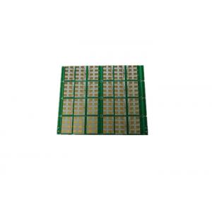
The whole plate gold plating we mean refers to "electroplating
gold", "electroplating nickel gold plate", "electroplating gold",
"electric gold" "electric nickel gold plate", a distinction between
soft gold and hard gold (generally hard gold is used for gold
fingers). The principle is to dissolve nickel and gold (commonly
known as gold salt) in chemical water and dip the PCB into the
electroplating cylinder. The nickel gold coating is generated on
the copper foil surface of the circuit board. The electric nickel
gold is widely used in electronic products because of its high
hardness, wear resistance and difficult oxidation.
What are the benefits of PCB Gold plating?
Anti-oxidation, protection of the bottom layer Ni and copper
Gold wear resistance, good reliability
Gold finger, mainly using the good conductivity of gold
RF is Radio Frequency, which refers to radio frequency, high
frequency signal,RF PCB can be defined as a PCB with an analog
signal in the frequency range of 30MHz to 6GHz. However, whether a
lumped or distributed parameter model is used can be determined
according to the formula.
RF printed circuit board PCB thickness is usually an integral
multiple of 0.2mm, such as 0.8mm, 1.0mm, 1.6mm, etc. Sometimes
printed circuit board sheet thickness is also expressed in inches.
The specific thickness should be based on the results calculated by
the impedance control.The precision of the characteristic impedance
must be strictly controlled in the manufacture of RF circuit
boards.
| item | Mass production | Small batch order | |
| Laminate | FR-4,High TG,Rogers,Taconic,Isola,F4B,Arlon,Teflon,Main in RF PCB | ||
| Maximum board size | 610*460mm | 610*460mm | |
| Board thickness | 0.3-3.5mm | 0.2-6.0mm | |
| Minimum line width/space | 0.1/0.1mm | 0.076/0.076mm | |
| Minimum line gap | +/-15% | +/-10% | |
| Outer layer copper thickness | 140um | 210um | |
| Inner layer copper thickness | 70um | 150um | |
| Min.finished hole size(Mechanical) | 0.2mm | 0.15mm | |
| Min.finished hole size (laser hole) | 0.1mm | 0.1mm | |
| Aspect ratio | 10:01 | 13:01 | |
| Flash Gold | 0.025-0.075um | 0.025-0.5um |
| Immersion Gold | 0.05-0.1um | 0.1-0.2um | |
| Sn/Pb Hasl | 1-70um | ||
| Leadfree Hasl | 1-70um | ||
| Immersion Silver | 0.08-0.3um | ||
| OSP(Entek) | 0.2-0.4um | ||
| Gold Finger | 0.375um | >=1.75um | |
| Hard Gold Plating | 0.375um | >=1.75um | |
| Immsion Sn | 0.8um | ||

