Product Details
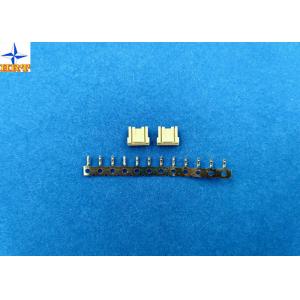
1.00mm Pitch Circuit Board Wire Connectors Crimp Housing Single Row
6 position
1, The detailed specification excel
| Basic size information |
| Category | Crimp housings |
| Suitable terminals | A1007T series |
| Lock to mating part | With |
| Panel mount | No |
| Circuits | 6 pins |
| Wire insulation diameter | 0.80mm Max. |
| Terminal material | phosphor bronze |
| Terminal finish | tin-plated or gold-flash |
|
| Electrical properties |
| Current Rating | 1A AC, DC |
| Voltage Rating | 60V AC, DC |
| Contact Resistance | 20mΩ Max |
| Insulation Resistance | 100mΩ min |
| Withstanding Voltage | 600V AC/minute |
|
| Mechanical properties |
| Temperature range | -25℃ to 85 ℃ |
|
| Other information please kindly check the following picture. |
2, Related drawing and report
Folllowing pictures are out testing report and exact engineering
drawing for your information, please kindly check it, wish it can
help you to get what you really need.
5. Mechanical Performance
| Test Description | Procedure | Requirement | | 5-1 | Actuator Insertion & Withdrawal Force | Insert and withdraw connectors at the speed rate of 25±3mm /
minute. | Refer to paragraph 7 | | 5-2 | Crimping Pull Out Force | Fix the crimped terminal, apply axial pull out force on the wire at
the speed rat of 25±3mm / minute.(Based upon JIS C5402 6.8) | AWG#30 | 1.0kgf (Min) | | AWG#32 | 1.0kgf (Min) | | 5-3 | Terminal Insertion Force. | Insert the crimped terminal into the housing. | 0.80kgf (Max.) | | 5-4 | Terminal/Housing Retention Force. | Apply axial pull out force at the speed rate of 25±3mm / minute on
the terminal assembled in the housing. | 0.80kgf (Min.) | | 5-5 | Pin Retention Force | Apply axial push force at the speed rate of 25±3mm / minute | 0.50kgf (Min.) | | 5-6 | Locking Strength (Housing) | Mate the connectors and apply the force by pulling axially the
housing at a rate of 25 ± 6 mm per minute. Strength is determined when locking device
disengaged locking, or is broken by the load. | 1.50kgf (Min.) | | 5-7 | Durability | When mated up to 30 cycles repeatedly by the rate of 10 cycle per
minute. | Contact Resistance 20mΩ (Max.) | | 5-8 | Vibration | Amplitude: 1.5mm P-P Sweep time: 10-55-10 Hz in 1 minute Duration: 2 hours in each
X.Y.Z. axes. (Based upon MIL-STD-202 Method 201A) | Appearance No Damage. Contact Resistance 20mΩ (Max.) Discontinuity 1 μsec.(Max.) | | 5-9 | Physical Shock | 490m/s²{50G},3 strokes in each X.Y.Z. axes. (Based upon JIS
C0041/MIL-STD-202 Method 213B Cond. A) |
|
6. Environmental Performance And Others
| Test Description | Procedure | Requirement | | 6-1 | Temperature Rise | Carrying rated current load.(Based upon UL 498) | 30℃(Max.) | | 6-2 | Heat Resistance | 105±2℃,96 hours (Based upon JIS C0021/MIL-STD-202 Method 108A Cond.
A) | Appearance No Damage. Contact Resistance 20mΩ (Max.) | | 6-3 | Cold Resistance | -40±3℃,96 hours (Based upon JIS C0020) | | 6-4 | Humidity | Temperature: 60±2℃ Relative Humidity : 90~95% Duration: 96 hours (Based upon JIS C0022/MIL-STD-202 Method 103B Cond. B) | Appearance No Damage. Contact Resistance 40mΩ (Max.) Insulation Resistance 100MΩ (Min.) Dielectric Withstanding Voltage Must meet 4-3 | | 6-5 | Temperature Cycling | 5 cycles of: a) -40℃ 30 minutes b) +105℃ 30 minutes (Based upon JIS C0025) | Appearance No Damage. Contact Resistance 20mΩ (Max.) | | 6-6 | Salt Spray | Tin-plated 24 hours / Gold- plated 48 hours exposure to a salt
spray from the 5±1% solution at 35±2℃. (Based upon JIS
C0023/MIL-STD-202 Method 101C Cond. B) | | 6-7 | SO2 Gas | 24 hours exposure to 50±5ppm. SO2 gas at 40±2℃. | | 6-8 | NH3 Gas | 40 minutes exposure to NH3 gas evaporating from 28% Ammonia
solution. |
| 6-9 | Solderability | Soldering Time: 5±0.5 sec. Solder Temperature: 245±5℃ | Solder Wetting 95% of immersed area must show no voids, pin holes | | 6-10 | Resistance to Soldering Heat | When reflowing Refer to paragraph 8 Solder iron method Soldering Time: 5±0.5 sec. Solder Temperature: 370℃ ~ 400℃ | Appearance No Damage. |
7. Actuator Insertion/Withdrawal Force [Unit : kgf] | Circuits | At Initial | | Insertion (Max.) | Withdrawal 1st (Min.) | Insertion 6th (Max.) | Withdrawal 30th (Min.) | | Single | 1.5 | 0.03 | 0.03 | 0.03 | | 02 | 1.7 | 0.06 | 0.06 | 0.06 | | 03 | 1.9 | 0.07 | 0.07 | 0.07 | | 04 | 2.0 | 0.08 | 0.08 | 0.08 | | 05 | 2.2 | 0.09 | 0.09 | 0.09 | | 06 | 2.3 | 0.12 | 0.12 | 0.12 |
8. Applicable Wires: AWG Size: AWG#30 UL1571 Insulation OD: Φ0.70mm AWG#32 UL10064 Insulation OD: Φ0.42mm 9. Crimping Condition | Wire Specification | Crimp Height(mm) | Crimp Width(mm) | | UL | AWG | OD | A | B | W1 | W2 | | UL1571 | #30 | 0.70 | 0.51-0.54 | 0.65-0.70 | 0.70-0.75 | 0.80 MAX. | | UL10064 | #32 | 0.42 | 0.48-0.52 | 0.60-0.65 | 0.70-0.75 | 0.80 MAX. |
|
3, Applicated field of this product by graphical representation
This product is widely used in computer, household appliance and so
on. You can get this message through the pictures.
Company Profile
12-year Experience of Manufacturing Connectors
Established in 2004, Xinpei is your reliable supplier for most of
connectors. Our products are widely trusted by reputable and
famouse manufacturers of household appliances, computer
peripherals, medical equipment, locomotives, telecommunication
device and other relative field.
Offering One-stop Sourcing Solutions for International Buyers
At our ISO 9001:2008 certified factory in Dongguan, mainland China,
we make UL-listed goods by using automatic equipment for uniform
product quality. By our integrated molding, mass production and
assembly services are carried out by 100 skilled workers and the
professional account executive can offer an one-stop sourcing
solution to all international buyers.
Advanced Machines from Japan and Taiwan
We use advanced machinery from Japan and Taiwan to guarantee
efficient and precise manufacturing. We have a commitment in
delivering superior quality products at competitive prices.
Our advantages are as following:
- We offer complete end-to-end customized manufacturing solutions
- We have four mechanism engineers to refine your design for
production
- We skillfully use AutoCAD, SolidWorks and Pro/E software to design
your customized project
- Our materials are sourced from Switzerland, Japan and Taiwan
- Reputable manufacturers like Amphenol and AOC trust and cooperate
with us for many years
- We own advanced inspection equipment like X-ray testing machine,
high pressure testing machine projector, fully automatic tension
meter, salt spray testing machine, insulation pressure testing
machine and 3D optical image measuring testers to ensure the
highest quality possible
- We accept small quantity orders
- Reply inquiries within eight hours
- We have more than 15 years of experience in handling OEM and ODM
orders
Contact Us Now
We are looking forward to establishing long-term business
relationship with you in the near future. So please inquire to us
today and receive our fast reply within eight hours.