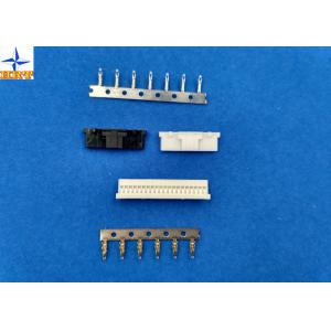
UL94V-0 Wire Board Connector , 1 Row Circuit Wire Connectors With
Lock / Bump A1253HA
1, The specification of the product including basic size
information, electrical and mechanical properties.
| Basic size information |
| Color | White |
| Pitch | 1.25mm |
| Mating lock | With |
| Bump | With |
| Material | PA66 |
| Flammability | UL94V-0 |
| Wire Insulation Diameter | 1.00mm Max. |
| Mounting side | Standard on-Board |
| Terminals material | phosphor bronze, tin-plated/gold-flash finish |
|
| Electrical properties |
| Current Rating | 1A AC, DC |
| Voltage Rating | 150V AC, DC |
| Contact Resistance | 30mΩ Max |
| Insulation Resistance | 500mΩ min |
| Withstanding Voltage | 500V AC/minute |
|
| Mechanical properties |
| Operating Temperatureemperature range | -25℃ to 85 ℃ |
| Terminal Insertion Force | 0.80kgf (Max.) |
| Terminal/Housing Retention Force | 0.50kgf (Min.) |
| Pin Retention Force | 0.50kgf (Min.) |
|
| Other information please kindly check the following picture. |
2, Introduction for this series products
Please kindly notice that the A1253 series product, if you can buy
this product as a set, the price will be very reasonale and
favorable.
1, Terminals:A1253-T & A1253-T-A
2, Housing: With lock type: A1253H-NP; Without lock type: A1253HA-NP
3, Wafer: Right angle type(90°):A1253WR-S-NP & A1253WR-SF-NP &
A1253WRA-S-NP
Vertical type(180°): A1253WVA-S-NP
3, Related engineering drawing and report
Please kindly check the following engineering drawing to confirm
the size, wish it's what you really need.
Dimension drawing
Testing report
3. Ratings & Applicable Wires
| Item | Standard | | Rated Voltage (Max.) | 150V AC/DC | Insulation O.D. 0.90mm (Max.) | | Rated Current (Max.) And Applicable Wires | AWG#28 | 1A AC/DC | | AWG#30 | 1A AC/DC | | AWG#32 | 1A AC/DC | | Ambient Temperature Range | -25℃ ~ +85℃* |
*: Including terminal temperature rise
4. Electrical Performance
| Test Description | Procedure | Requirement | | 4-1 |
Contact Resistance
| Mate connectors, measure by dry circuit, 20mV max., 10mA.(Based
upon JIS C5402 5.4) | 20mΩ (Max.) | | 4-2 | Insulation Resistance | Mate connectors, apply 500V DC between adjacent terminal or ground.
(Based upon JIS C5402 5.2/MIL-STD-202 Method 302 Cond. B) | 500MΩ (Min.) | | 4-3 | Dielectric Withstanding Voltage | Mate connectors, apply 500V AC (rms) for 1 minute between adjacent
terminal or ground. (Based upon JIS C5402 5.1/MIL-STD-202 Method
301) | No Breakdown. | | 4-4 | Contact Resistance on Crimped Portion | Crimp the applicable wire on to the terminal, measure by dry
circuit, 20mV (Max.)., 10mA. | 5mΩ (Max.) |
5. Mechanical Performance
| Test Description | Procedure | Requirement | | 5-1 | Actuator Insertion & Withdrawal Force | Insert and withdraw connectors at the speed rate of 25±3mm /
minute. | Refer to paragraph 7 | | 5-2 | Crimping Pull Out Force | Fix the crimped terminal, apply axial pull out force on the wire at
the speed rat of 25±3mm / minute.(Based upon JIS C5402 6.8) | AWG#28 | 1.0kgf (Min) | | AWG#30 | 0.8kgf (Min) | | AWG#32 | 0.5kgf (Min) | | 5-3 | Terminal Insertion Force. | Insert the crimped terminal into the housing. | 0.80kgf (Max.) | | 5-4 | Terminal/Housing Retention Force. | Apply axial pull out force at the speed rate of 25±3mm / minute on
the terminal assembled in the housing. | 0.50kgf (Min.) | | 5-5 | Pin Retention Force | Apply axial push force at the speed rate of 25±3mm / minute | 0.50kgf (Min.) | | 5-6 | Latch Yield Strength | Mate connectors and pull apart until both latches break at the
speed rate of 25±3mm / minute | 02P: 0.8kgf (Min.) ; 03P: 1.2kgf (Min.) 04P: 2.0kgf (Min.) ; 5~10P: 2.2kgf (Min.) 11-15P: 2.3kgf (Min.) ;20P: 2.4kgf (Min.) 30P: 2.45kgf (Min.) | | 5-7 | Durability | When mated up to 50 cycles repeatedly by the rate of 10 cycle per
minute. | Contact Resistance 40mΩ (Max.) | | 5-8 | Vibration | Amplitude: 1.5mm P-P Sweep time: 10-55-10 Hz in 1 minute Duration: 2 hours in each
X.Y.Z. axes. (Based upon MIL-STD-202 Method 201A) | Appearance No Damage. Contact Resistance 40mΩ (Max.) Discontinuity 1 μsec.(Max.) | | 5-9 | Physical Shock | 490m/s²{50G},3 strokes in each X.Y.Z. axes. (Based upon JIS
C0041/MIL-STD-202 Method 213B Cond. A) |
|
6. Environmental Performance And Others
| Test Description | Procedure | Requirement | | 6-1 | Temperature Rise | Carrying rated current load.(Based upon UL 498) | 30℃(Max.) | | 6-2 | Heat Resistance | 85±2℃,96 hours (Based upon JIS C0021/MIL-STD-202 Method 108A Cond.
A) | Appearance No Damage. Contact Resistance 40mΩ (Max.) | | 6-3 | Cold Resistance | -25±3℃,96 hours (Based upon JIS C0020) | | 6-4 | Humidity | Temperature: 40±2℃ Relative Humidity : 90~95% Duration: 96 hours (Based upon JIS C0022/MIL-STD-202 Method 103B Cond. B) | Appearance No Damage. Contact Resistance 40mΩ (Max.) Insulation Resistance 50MΩ (Min.) Dielectric Withstanding Voltage Must meet 4-3 | | 6-5 | Temperature Cycling | 5 cycles of: a) -55℃ 30 minutes b) +85℃ 30 minutes (Based upon JIS C0025) | Appearance No Damage. Contact Resistance 40mΩ (Max.) | | 6-6 | Salt Spray | Tin-plated 24 hours / Gold- plated 24 hours exposure to a salt
spray from the 5±1% solution at 35±2℃. (Based upon JIS
C0023/MIL-STD-202 Method 101C Cond. B) | | 6-7 | SO2 Gas | 24 hours exposure to 50±5ppm. SO2 gas at 40±2℃. | | 6-8 | NH3 Gas | 40 minutes exposure to NH3 gas evaporating from 28% Ammonia
solution. |
| 6-9 | Solderability | Soldering Time: 5±0.5 sec. Solder Temperature: 245±5℃ | Solder Wetting 95% of immersed area must show no voids, pin holes | | 6-10 | Resistance to Soldering Heat | When reflowing Refer to paragraph 8 Solder iron method Soldering Time: 5±0.5 sec. Solder Temperature: 370℃ ~ 400℃ | Appearance No Damage. |
7. Actuator Insertion/Withdrawal Force
SMT (WITHOUT A LOCK) [Unit : kgf] LOCK [Unit : kgf] | Circuits | At Initial | | Circuits | At Initial | | Insertion (Max.) | Withdrawal (Min.) | | Insertion (Max.) | Withdrawal (Min.) | | Single | 0.20 | 0.04 | | Single | 0.40 | 0.20 | | 02 | 0.70 | 0.15 | | 02 | 0.75 | 0.80 | | 03 | 0.85 | 0.20 | | 03 | 1.13 | 1.20 | | 04 | 1.00 | 0.25 | | 04 | 1.50 | 2.00 | | 05 | 1.15 | 0.30 | | 05 | 1.88 | 2.20 | | 06 | 1.30 | 0.35 | | 06 | 2.25 | 2.20 | | 07 | 1.45 | 0.40 | | 07 | 2.63 | 2.20 | | 08 | 1.60 | 0.45 | | 08 | 3.00 | 2.20 | | 09 | 1.75 | 0.50 | | 09 | 3.38 | 2.20 | | 10 | 1.90 | 0.55 | | 10 | 3.80 | 2.20 | | 11 | 2.05 | 0.60 | | 11 | 4.13 | 2.30 | | 12 | 2.20 | 0.65 | | 12 | 4.50 | 2.30 | | 13 | 2.35 | 0.70 | | 13 | 4.88 | 2.30 | | 14 | 2.50 | 0.75 | | 14 | 5.25 | 2.30 | | 15 | 2.65 | 0.80 | | 15 | 5.63 | 2.30 | | 20 | 3.40 | 1.05 | | 20 | 7.50 | 2.35 | | 25 | 4.15 | 1.30 | | 25 | 9.38 | 2.35 | | 30 | 4.90 | 1.55 | | 30 | 11.25 | 2.40 |
|
4, FAQ
Q:Do you allow multiple design per setup?
A:Yes.We accept OEM service and allow multiple design per setup.
Q:How long does shipping take?
A:It depends on the destination location and quantity. In most
developed world, delivery by Fed x/UPS/DHL is normally 3-5
days(excluding weekends).
Q: How is the goods packaged ?
A: Usually in bags, tube, pipe, plated & carton
5, Various payment & delivery way
In order to make you get product quickly and send money easily, we
can offer differenct payment terms
for you.
Payment Policy
| Total value of order(Currency: USD ) | Suggested payment terms |
| Less than USD350 | PayPal or Wester Union |
| |
| Between USD350 and USD500 | Western Union |
| |
| Between USD500 and USD5000 | TT |
| |
| Over USD5000 | TT or L/C at sight |
The commision fee of TT/PayPal/ Letter of credit will be shared by
us together.
Delivery ways