
Add to Cart
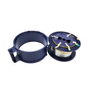
Telecom OTDR Test Bare Fiber G652D G657A 20km Coring With Connectors SC FC LC 20KM
When optical time domain reflectors (OTDR) are used to measure optical fiber, it is sometimes encountered that the optical fiber link is short. When measuring short optical fiber link, the bigger attenuation value (xxdb/km) is often obtained, which makes the attenuation index unable to obtain a better evaluation. Why?
Because of the short optical fiber link (generally less than 1km), OTDR measured the curve with certain volatility, which affected the final numerical calculation. Among the technical parameters describing OTDR, there is an index about the linearity. The general index of OTDR is 0.05db/db (e600c:0.05db/db, n3900a:0.03db/db). In fact, this indicator describes the fluctuation range of OTDR curve.
Therefore, for short fiber, the accuracy of OTDR measurement is challenged. This problem is also a common problem facing OTDR lock. So what methods can we reduce this impact? How can we get a better test result?
1. Add 2km test false fiber
The effect will be reduced as the fiber length is increased due to the addition of 2km test false fiber. A more satisfactory result should be available.
But because of the increase of length and the introduction of test error, this method has some errors brought by the test method. But as the test data of the project quality, it has a considerable reference value.
2. Measure link loss with light source and optical power meter, and measure length with OTDR
The progress of the loss measurement is improved because the optical power meter measures the link loss close to the standard loss measurement method by using the light source. Of course, for the segment fiber, the higher resolution accuracy level of the optical palace garbage is used to reduce the error. The length measurement was obtained by OTDR. The attenuation value of unit length can be obtained by dividing the loss value by the length value.
3. OTDR measurement curve is only used as reference, and OTDR measurement focuses on removing link obstacles.
In short fiber measurement, OTDR measurement curve is best used as a reference, as a qualitative basis, rather than as a quantitative basis.
Specification of Single mode fiber
| ITEM | Value |
| Mode diameter | (8.6-9.5)±0.7um |
| Cladding diameter | 125±1um |
| Concentricity deviation | ≤0.8um |
| Cladding out of roundness | ≤0.2% |
| Cut off wavelength of optical cable | ≤1260um |
| Macrobending loss 1550nm | ≤0.3dB |
| (37.5mm radius 100 turns) 16xx1nm | ≤0.3dB |
| Screening stress | ≥0.69GPa |
| Zero dispersion wavelength λ | 1300nm≤λ ≤1324nm |
| zero dispersion slope s | ≤0.093ps/um |
| Polarization mode dispersion coefficient of uncalled fiber | ≤xxps(km)1/2 |
| Attenuation number of optical cable | 1300nm≤0.3dB/km ≤0.28dB/km |
| Yyyy nm- - xx dB/km | |
| 16xx1nm - ≤0.28dB/km | |
| Polarization mode dispersion coefficient of optical cable | M -20 optical fiber segments |
| Q -0.01% | |
| PMD-≤0.5ps/(km)1/2 |
Features