Deep Sea Automatic Engine Control Module DSE520
Brand Name:AE
Certification:ISO9001:2008
Model Number:DSE520
Minimum Order Quantity:1 pc
Delivery Time:2-3 working days
Payment Terms:T/T, Paypal, Western Union
Contact Now
Add to Cart
Active Member
Address:
China
Supplier`s last login times:
within 1 hours
Product Details
Company Profile
Product Details
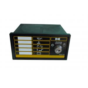
DSE520 Auto Start Control Module
The Model 520 is an Automatic Engine Control Module designed to automatically start and stop the engine
The Model 520 is an Automatic Engine Control Module designed to
automatically start and stop the engine. It will indicate the
operational status and fault conditions, automatically shut down
the engine and indicate the engine failure by a flashing LED on the
front panel. Other simultaneous faults are indicated by steady LED.
Selected operational sequences, timers and alarms can be altered by
the customer by using either the 807 hand held calibration unit or
a PC and the 808 interface. This also provides the operator with
'real-time' diagnostic facilities to monitor the operation of the
system either locally or remotely.
Remote PC-controlled engine starting and stopping is also featured.
Operation of the module is via a three position rotary switch (key-switch option available) mounted on the front panel with STOP, AUTO and MANUAL positions.
Microprocessor control allows for enhanced operation. The module
features a comprehensive list of timers and pre-configured
sequences. This allows complex specifications to be achieved
Configurable expansion facilities are provided.
Main features
CONFIGURABLE INPUTS
Configurable inputs are available for:
*Low Oil Pressure
*High Engine Temperature
*Remote Start.
This allows the module to function with normally open or normally
closed switches.
Four fully configurable auxiliary inputs are provided to give
protection expansion.These can be selected to be indication,
warning or shutdown inputs either immediate or held off during
start up.
ALARM CHANNELS
Multiple alarm channels are provided to monitor the following:
*Under/Overspeed
*Charge Fail
*Emergency Stop
*Low oil pressure
*High engine temperature
*Fail to Start
*Fail to stop
*Loss of speed sensing
*Programmable inputs as selected
First up alarm is indicated by a flashing LED. Subsequent simultaneous alarms are displayed by a steady LED.
Specification
DC SUPPLY
CONTINUOUS VOLTAGE RATING
8 to 35 V Continuous.
CRANKING DROPOUTS
Able to survive 0 V for 50 mS,
providing supply was at least 10 V
before dropout and supply recovers
to 5V. This is achieved without the
need for internal batteries.
MAXIMUM OPERATING CURRENT
290 mA at 12 V. 210 mA at 24 V.
MAXIMUM STANDY CURRENT
50 mA at 12 V. 30 mA at 24 V.
CHARGE FAIL EXCITATION RANGE
0 V to 35 V
INPUTS
A;TERNATOR INPUT RANGE
15 - 300 V ac RMS
ALTERNATOR INPUT FREQUENCY
50 - 60 Hz at rated engine speed.
Magnetic Input Range:
0.5 V to +/- 70 V (Clamped by
transient suppressors)
MAGNETIC iNPUT FREQUENCY
10Hz to 10,000 Hz
OUTPUTS
START RELAY OUTPUT
16 Amp DC at supply voltage.
FUEL RELAY OUTPUT
16 Amp DC at supply voltage.
AUXILLIARY RELAY OUTPUTS
5 Amp DC at supply voltage.
DIMENSIONS
OVERALL
72 X 144 X 118.5mm (Excluding
switch)


Deep Sea Automatic Engine Control Module DSE520
Inquiry Cart
0