
Add to Cart
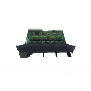
The IC697MDL753 is a 5/48 Volt DC, 0.5 Amp, Negative Logic,
32-Point Output module from the GE Fanuc 90-70 Series. This module
provides 32 points divided into 2 isolated groups of 16 points
each. The rated voltage on this module can be 5 volts DC or 10 to
60 volts DC. It provides a high degree of inrush current at 10 to
60 volts which makes the outputs suitable for a wide range of loads
which have such characteristics. It also operates at TTL levels.
The outputs are ideal for a wide spectrum of loads. This is due to
the effective delivery of high inrush current which is between 10
to 60 volts. You can spot LED indicators at the top of each logic
point of the PLC module. Their primary function is to display the
ON-Off status of each logic point of the PLC. Jumpers and DIP
switches are not required for the configuration of I/O references
located on the module. The configuration of the module is achieved
using Microsoft’s MS-DOS or Windows NT & 95 operating systems
over the TCP/IP protocol. Programming devices can be either
compatible personal computers, PS/2, AT or IBM.
As mentioned earlier, the IC697MDL753 PLC output module is compatible with a wide variety of loads which include indicators, motor starters, solenoids and TTL interfaces. Due to the significant overall heat dissipation with each group of modules, the maximum current is set to 4 Amps. Each output can deliver a current rating exceeding its long-term rating. The ability of each output point to deliver a current largely depends on the device’s current rating as well as the duration the device is powered ON. Since the Logic output module has no replaceable fuses, a ¾ Amp 250-volt fuse is connected externally to each output point. The fuse models are either Little Fuse 312.750 or Bussmann AGC-3/4.
There are certain field wiring procedures that need to be followed
when setting up the modules. First, ensure that you’ve turned off
the power during removal or installation of terminal boards.
The jackscrew that secures the terminal board in place can be
located when opening the hinged door on the module. The screw is
then turned in a counter clockwise direction to loosen the
detachable terminal board. The board is thereafter removed by
grabbing it and swinging it outward. Be cautious when removing the
terminal board. The hinged door may become damaged if it is used to
remove the terminal board. The board can accommodate wires ranging
from AWG#22 (0.36mm2) right through AWG #14 (2.10mm2). Kindly note
that a .135-inch maximum diameter is not to be exceeded when using
the AWG#14 (2.10mm2) wire.
For a proper connection, you can terminate two wires on any terminal if the wires are of the same size. The terminal board accepts a maximum of 40 AWG#14 wires. If the said wires are to be used, then the wire markers should be placed accordingly. The terminal board is designed to accept a maximum of (40) AWG #14 (2.10 mm2) wires. To provide ample space for the hinged door to close, wire markers should be placed at least 8 inches (203 mm) from termination end when using the AWG #14 wires. After connections are completed for all modules in the rack, wire bundles must be secured. It’s recommended that cable ties are firmly wrapped round the wire bundles. Additional cable ties are used when larger wire bundles are involved. Each module comes with a door label insert which displays its wiring information. After completion of the field wiring, the terminal board should be firmly secured on the rack. For ideal ventilation of the module, a 6-inch clearance is recommended above and below the rack grill.
| Rated Voltage: | 5 volts DC or 10 to 60 volts DC |
| Number of Outputs: | 32 Outputs (2 groups of 16) |
| Output Current: | 16 mA/ point @ 5 VDC, 0.5 Amps/ point, 4 Amps/ group @ 10 to 60 VDC |
| Current Required: | 0.25 Amps |
| Output Voltage Range: | 5 volts DC or 10 to 60 volts DC |
| DC Power: | Yes |
Rated Voltage: OutputsperModule: | 5 volts DC (" 5%) 10 to 60 volts DC 32 (two groups of 16 outputs each) |
| Isolation: | 1500 volts - any output to backplane 500 volts between input groups |
Output VoltageRange: OutputCurrent 5 volts DC 10 to 60 volts DC | 5 volts or 10 to 60 volts 16 mA maximum per point 0.5 amps maximum per point 4 amps maximum per group |
OutputCharacteristics Inrush Current 10 to 60 volts DC: Output VoltageDrop: 5 volts DC: 10 to 60 volts DC: ResponseTime-On: ResponseTime-Off: OutputLeakage: 5 volts DC: 10 to 60 volts DC: | 5 amps maximum for 20 ms |
| 0.5 voltsmaximum (16 mA) | |
| 1 volt (2 ohms) maximum | |
| 1 ms typical | |
| 1 ms typical | |
| 250 ïAmaximum | |
| 1mAmaximum | |
| Current Required from 5 V Bus: | .25 amp |
| VME | System designed to support the VME standard C.1 |

