
Add to Cart
48 port 19 inch rack mount multimode fiber optic patch panel
Product description:
48 port 19 inch rack mount multimode fiber optic patch panel
include MPO / MTP cable and adapters are also known as fiber
distribution panels. They make it easy to terminate fiber optic
cables and provide access to the cable’s individual fibers for
cross connection.
A basic fiber optic panel is typically a metal enclosure that
encloses the adapter panels and fiber splice trays. Splice trays
allow fibers to be fused together with fiber optic pigtails which
in turn are plugged into the fixed inside ports of the adapter
panels.
The inside ports of the panel is usually fixed, meaning that the
cables aren’t disconnected at any point. The outside ports of the
panel is reserved for fiber patch cables that can be plugged and
unplugged frequently to arrange the connections between devices as
needed.
Fiber patch panel has two compartments. One contains the bulkhead
receptacles or adapters, and the other is used for splice tray and
excess fiber storage.
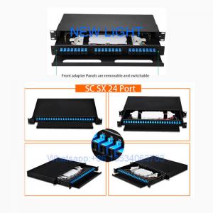
slide-out rack mount fiber optic enclosure, loaded with 3 pcs of LC multimode duplex adaptor and splice tray ... 6 port 19-inch slide-out rack mount fiber optic closure, loaded with 6 pcs of ST singlemode adaptor and splice tray.
There different models to fit for 12 core fiber,24 core fiber,36 core fiber,48 core fiber, 72 core fiber,96 core fiber,144 core fiber applications. They can be with different adapter interface including the SC, ST, FC, LC MTRJ,e2000 etc . Related fiber accessories and pigtails are optional.
Application:
1. Telecommunications subscriber loop
2. Fiber to the home (FTTH)
3. LAN/WAN
4. CATV
Features:
Used to the branch connection of optical cable termination
19'' Standard Structure, Rack mounting
Available for the installation of adaptors
Drawer Structure, Easy for Operation.
Compact design for space saving
Easy for management and operation
Standard size, light weight and reasonable structure
Mechanical and environmental characteristics:
| Projects | Parameter |
| Operating temperature | -25℃~+40℃ |
| Storage temperature | -25℃~+55℃ |
| Relative humidity | ≤85%(+30℃) |
| Air pressure | 70Kpa~106Kpa |
| Color | Black |
Dimension:
| Model | fiber quantity | Height | Dimension(LxWxH) |
| rack mount | 12 /24 /48 /96 core | 1U | 430*354.1*44mm |
Polarity
For fiber links to properly send data, the transmit signal (Tx) at
one end of the cable must match the corresponding receiver (Rx) at
the other end. The purpose of any polarity scheme is to ensure this
continuous connection, and this becomes a bit more complex when
dealing with multi-fiber components. Industry standards call out
three different polarity methods—Method A, Method B and Method C.
And each method uses different types of MPO cables.
Method A uses Type A straight-through MPO trunk cables with a key
up connector on one end and a key down connector on the other end
so that the fiber located in Position 1 arrives at Position 1 at
the other end. When using Method A for duplex applications, making
the transceiver-receiver flip is required in a patch cord at one
end.
Method B uses key up connectors on both ends to achieve the transceiver-receiver flip so that the fiber located in Position 1 arrives at Position 12 at the opposite end, the fiber located in Position 2 arrives at Position 11 at the opposite end and so on. For duplex applications, Method B uses straight A-B patch cords on both ends.
Method C uses a key up connector on one end and a key down on the
other end like Method A, but the flip happens within the cable
itself where each pair of fibers is flipped so that the fiber in
Position 1 arrivers at Position 2 at the opposite end and the fiber
in Position 2 arrives at Position 1. While this method works well
for duplex applications, it does not support parallel 8-fiber 40
and 100 Gig application and is therefore not recommended.
With three different polarity methods and the need to use the
correct type of patch cords for each, deployment mistakes can be
common. Thankfully, Fluke Networks’ MultiFiber™ Pro allows users to
test individual patch cords, permanent links and channels for
correct polarity.