
Add to Cart
Design Topology Diagram
Battery mode: Prioritize the battery power supply. When the battery reaches a low voltage, it will automatically switch to Mains electricity. After charge enough,the device will automatically switch to storage for battery.
System Capacity | 6kWh |
The System Efficiency | 85%±5% |
The System DOD | 80%DOD |
Min Energy Capacity | ≥6.451kWh |
Life Cycles | 25℃±2℃,0.3Ccharge and discharge,80%DOD,More than 2000times,(Capacity remain over 80%) |
Continuous Charge Current(A) | 50A |
Continuous Discharge Current(A) | 80A |
Charge and Discharge Rate at Full Power | 0.3C |
Battery Energy | 25°C 6.5kWh (100% DOD @ 1C rate) - 20°C 6.0 kWh(100% DOD @ 1C rate) |
Storage Temperature | Less 45°C suggested |
Self Discharge | 25°C,Per month≤5% |
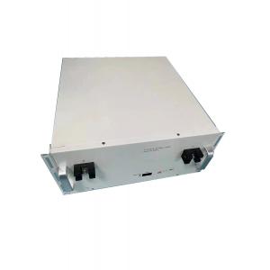
IP | IP67 |
Type | Inverter configuration (/)2-3kW Continuous power:(KW)2-3 Peak power:(KW)6 |
Parameters | Nominal Voltage:(Vdc)51.2 Charge Current:(A)0~30 Cutoff Voltage: (V)58.4 Max discharge current:(A)60 Grid Voltage range:90-250Vac Max input current:35A Frequency:45-65Hz The voltage from Mains electricity low voltage to battery mode:165Vac±5% The recovery voltage of Mains electricity mode low voltage: 75Vac±5% The voltage from Mains electricity high voltage to battery mode:265Vac±5% The recovery voltage of Mains electricity mode high voltage:55Vac±5% Inverter voltage range:220Vac±5%(Inverter mode) Frequency:50/60Hz±1%(Inverter mode) Output waveform: pure sine wave Efficiency: >90% (88% resistive load) Protection function: overvoltage and undervoltage protection,overload protection, short circuit protection, over temperatureprotection. |
| BMS | |
Discharge Current(A) | 100 |
Charge Voltage(V) | 58.4 |
Charge Current(A) | 50 |
Overcharge Protection Voltage(V) | 3.75±0.05 |
Over Discharge Protection Voltage(V) | 2.2±0.01 |
Charging Overcurrent Protection(A) | 150±20 |
Discharge Overcurrent Protection(A) | 300±50 |
Net WT. | 220KG |