
Add to Cart
Oilfield Drilling Fluids Mixing Mud Agitator Solid Control Equipment
Description of Products:
JB/W series agitator is an important part of solid control system of mud tank, which is mainly used in agitating and blending drilling fluid so as to control the depositions of solid particles in its tank cycling system and to keep the mud property of circulation stable and mixture uniform. This device has some major features as follows:
a) The reducer adopts worm and gear (see Fig. 4), with tight structure, good meshing performance and reliable work.
b) The reducer combines with explosion-proof motor, which is suit for rough operation condition in field.
c) The explosion-proof motor and reducer input shaft are directly connected through flexible coupling instead of belt, so the rotation speed of the agitating impeller is constant.
d) The strong agitation, broad conformance and overload-free current at starting are provided.
e) The horizontal explosion-proof motor is easy for installation, adjustment and replacement.
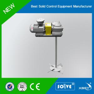
The agitator of our company consists of single impeller (see Fig. 1) and two impellers (see Fig. 2), and both of them include such eight models as JB/W2.2, JB/W3, JB/W5.5, JB/W7.5, JB/W11, JB/W15, JB/W18.5 and JB/W22. If users have no special requirements, the single-impeller agitator is no more than 2.4m deep, and the double-impeller agitator is more than 2.4m deep. User shall tell the depth of tank (from installation surface to the inner bottom plate),power and other requirements to us at ordering to provide better service for you.
Technical Parameters
| Item Model | JB/W2.2 | JB/W3 | JB/W5.5 | JB/W7.5 | JB/W11 | JB/W15 | JB/W18.5 | JB/W22 | ||
| Explosion-proof motor | Model | YB2-100L1-4 | YB2-100L2-4 | YB2-132S-4 | YB2-132M-4 | YB2-160M-4 | YB2-160L-4 | YB2-180M-4 | YB2-180L-4 | |
Power (kW) | 2.2 | 3 | 5.5 | 7.5 | 11 | 15 | 18.5 | 22 | ||
Voltage (V) | 380 (460) | 380 (460) | 380 (460) | 380 (460) | 380 (460) | 380 (460) | 380 (460) | 380 (460) | ||
Frequency (Hz) | 50 (60) | 50 (60) | 50 (60) | 50 (60) | 50 (60) | 50 (60) | 50 (60) | 50 (60) | ||
Rotating speed (rpm) | 1420 (1740) | 1420 (1740) | 1440 (1750) | 1440 (1750) | 1460 (1760) | 1460 (1760) | 1470 (1775) | 1470 (1775) | ||
| Reducer | Model | WPX120-i-A | WPX120-i-A | WPX135- i-A | WPX175- i -A | WPX175- i -A | WPX200- i -A | WPX250- i -A | WPX250- i -A | |
Transmission ratio (i) | 20 or 25 | 20 or 25 | 20 or 25 | 20 or 25 | 20 or 25 | 20 or 25 | 20 or 25 | 20 or 25 | ||
Impeller rotating speed (rpm) | 57, 70 or 71 | 57, 70 or 71 | 58, 70 or 72 | 58, 70 or 72 | 59, 70 or 73 | 59, 70 or 73 | 59, 71 or 74 | 59, 71 or 74 | ||
Impeller displacement (lpm) | 50Hz | 2870 | 7800 | 11870 | 15710 | 18750 | 26685 | 34280 | 43760 | |
| 60Hz | 3440 | 9360 | 14244 | 18852 | 22500 | 32022 | 41136 | 52512 | ||
Impeller diameter (mm) | Single impeller | 500 | 720 | 800 | 860 | 940 | 1040 | 1140 | 1240 | |
Two impellers | Upper:650 Nether:430 | Upper:720 Nether:480 | Upper:780 Nether:520 | Upper:900 Nether:600 | Upper:960 Nether:640 | Upper:1020 Nether:680 | Upper:1140 Nether:760 | |||
Weight(kg) (Less Shaft & Impeller) | 135 | 150 | 295 | 400 | 462 | 563 | 785 | 815 | ||
Overall size:L×W×H(mm) (Less Shaft & Impeller) | 817×494×498 | 817×494×498 | 954×549×583 | 1101×664×623 | 1222×664×665 | 1334×734×685 | 1445×888×770 | 1465×888×770 | ||
Structure and Operating Principle
The agitator is composed of explosion-proof motor, reducer, agitating impeller, base, flexible coupling and rigid coupling. Both explosion-proof motor and reducer are mounted on the base. The shaft extension side of the explosion-proof motor is connected with the input shaft (see Fig. 3) of the reducer through the flexible coupling. The agitating impeller is connected with the output shaft coupling (see Fig. 3) of the reducer through rigid coupling.
The agitating impeller, an important working part of the agitator, is composed of shaft, vane connection panel and vane which are welded together. When the explosion-proof motor starts up, the reducer input shaft is driven by flexible coupling to rotate. The explosion-proof motor comes out from the output shaft of reducer after slowing down speed and drives the agitating impeller to rotate. When the agitating impeller contacts with drilling fluid and makes it move in vortex, thus, the drilling fluid will not be deposited in solid phase to achieve uniform mixing and consistent density. The vane connection panel among vanes is able to prevent the solid particles of mud after shutdown from depositing below impeller. Thus, the resistance to vane from solid particles will be reduced at startup again, and the motor burning due to overloading may be avoided.