Add to Cart
CNC Flange Plate Drilling Machine Double Spindle Drill Heads Model PZ3020
Applicable Industry:
It is used for drilling holes in steel plates. The workpiece to be processed can be steel structure buildings, bridges, connecting plates on iron towers, or large flanges, heat exchanger tube plates, etc. The CNC drilling machine can make the whole process of drilling work to achieve a complete automation degree with high precision and high efficiency. It is suitable for drilling and processing of connecting plates, anchor plates, end plates, templates, flanges, structural parts and other parts of steel structures, bridges, power communication towers, thermal power station boiler brackets and other industries.
Equipment introduction:
1. The bed is composed of a machine base, a worktable and a frame-type support frame. The machine base is made of steel plate group welding, which is a welded steel structure and has been treated with aging. A frame-type support frame is installed on the worktable, and the frame-type support frame is installed in combination with a movable bracket, which is fixed by a butterfly screw. Tighten the butterfly screw to adjust the distance between the movable brackets to meet the support of the workpiece. The processing area is spacious, and there are four processing areas on the left and right. You can drill while loading and unloading workpieces, and at the same time, you can also program drilling processing files. Twelve quick-movable automatic hydraulic clamps are distributed around the worktable, which can clamp a single block or overlap multiple steel plates at one time. On the left and right sides of the machine base, a linear rolling guide rail pair with high bearing capacity is arranged for guiding the left and right brackets of the moving gantry. A set of drive mechanism consisting of AC servo motor, synchronous pulley and ball screw is arranged on one side of the machine base for the movement of the left and right brackets of the gantry, ensuring high positioning accuracy and repeatable positioning accuracy.
2. The gantry system consists of a movable gantry and a supporting system.
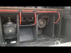
(1) Movable gantry
Because the machine base is fixed and the gantry moves, the equipment occupies a small area. The movable gantry is welded by steel plates and treated by artificial aging. Two linear rolling guide rail pairs and hydraulic power head are installed on the front side of the gantry, and a precision ball screw pair is installed above the gantry. The ball screw nut is connected and fixed with the back plate of the hydraulic power head through the fixing box. The ball nut is driven by the AC servo motor to rotate through the synchronous pulley, so that the hydraulic power head moves along the Y-axis direction to ensure the high precision of the drilling position and the repeated positioning accuracy. A guide rail flexible protective cover is installed on both sides of the power head.
(2) Support system
The support system consists of left and right brackets. The movable gantry is installed on the left and right brackets and is a right-angle bent plate welded steel structure. A ball screw nut is installed on the vertical surface of the left and right brackets. The ball screw in the ball screw nut is connected with the ball screw on the side of the bed, and the end of the ball screw is connected with the AC servo motor. When the AC servo motor on the side of the body rotates, it drives the ball nut to move axially on the ball screw, and the left and right brackets move on the guide rail (X axis).
Specifications:
| Item | Parameter | |
| Workpiece size | Width x length | 3000x2000mm |
| Thickness | Max.100 | |
| Diameter | 2000mm | |
| Spindle | Quick-change connector | Morse 4# |
| Drill diameter | Max.Φ50mm | |
| Speed-varying method | Inverter stepless speed regulation | |
| Rotate speed | 20-560r/min | |
| Stoke (Z axis) | 180mm | |
| Feeding | Hydraulic cylinder drive | |
| Workpiece Clamp | Clamp thickness | 15-100mm |
| Number of clamping cylinders | 12 | |
| Clamp force | 7.5kN | |
| Clamp open | Foot switch | |
| Cooling liquid | Method | Forced loop |
| Capacity | 300L | |
| Hydraulic | Clamp force | 6MPa(60kgf/cm2) |
| Fuel tank capacity | 90L | |
| Motor | Main spindle | 5.5kW |
| Hydraulic pump | 2.2kW | |
| Cooling pump | 0.45kW | |
| X-axis servo system | 2kW | |
| Y-axis servo system | 2x1kW | |
| Machine size | LxWxH | 6490×3880×2750mm |
| CNC axis quantity | 3 | |
| Positioning speed | 10000mm/min | |
| Machine size | LxWxH | 6490×3880×2750mm |