
Add to Cart
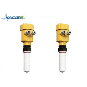
Non Contact Radar Fluid Level Meter For Measuring Solid And Low
Dielectric Constant
Product Overview
This radar level meter adopted 26G high frequency radar sensor, the
maximum measurement range can reach up to 80 meters. Antenna is
optimized further processing, the new fast microprocessors have
higher speed and efficiency can be done signal analysis, the
instrumentation can be used for reactor, solid silo and very
complex measurement environment
Principle
Radar level transmitter antenna microwave pulse is narrow, the
downward transmission antenna. Microwave exposure to the medium
surface is reflected back again by the antenna system receives,
sends the signal to the electronic circuit automatically converted
into level signals (because the microwave propagation speed,
electromagnetic wave to reach the target and the reflected back to
the receiver this time is almost instantaneous)
A Range set B Low adjustment C High D Blind area
Datum Measurement:Screw thread bottom or the sealing surface of the
flange
Note:Make sure the radar level meter the highest level cannot enter the
measuring blind area (Figure D shown below).
The Characteristics of 26G Radar Level Meter
Small antenna size, easy to install; Non-contact radar, no wear, no
pollution.
Almost no corrosion, bubble effect; almost not affected by water
vapor in the atmosphere, the temperature and pressure changes.
Serious dust environment on the high level meter work has little
effect.
A shorter wavelength, the reflection of solid surface inclination
is better.
Beam angle is small, the energy is concentrated, can enhance the
ability of echo and to avoid interference.
The measuring range is smaller, for a measurement will yield good
results.
High signal-to-noise ratio, the level fluctuation state can obtain
better performance.
High frequency, measurement of solid and low dielectric constant of
the best choice.
Technical Parameters
| Housing | ||
Seal between housing and housing cover | Silicone rubber | |
| Housing window | Polycarbonate | |
| The ground terminal | Stainless steel | |
| The power supply voltage | ||
| Two wire | The standard type | (16 ~ 26) V DC |
| Intrinsically safe | (21.6 ~ 26.4) V DC | |
| Power dissipation | max 22.5mA / 1W | |
| Allowable ripple | - <100Hz | Uss<lV |
| - (100~100K) Hz | Uss<l0mV | |
| The cable parameters | ||
| Cable entrance / plug | 1 M20xl.5 cable entrance | |
| 1 blind plug | ||
| Terminal | Conductor cross section 1.0mm² | |
| Output | The output signal | (4 ~ 20) mA |
| Communication protocol | HART | |
| Resolution | 1.6μ A | |
| Fault signal | Constant current output; 20. 5mA, 22mA, 3.9mA | |
| The integral time | (0 ~ 50) s, adjustable | |
| Blind zone | the ends of the antenna | |
| Max. measuring range | 80m | |
| Microwave frequency | 26GHz | |
| Communication interface | HART communication protocol | |
| The measurement interval | about 1 second (depending on the parameter settings) | |
| Adjustment time | about 1 second (depending on the parameter settings) | |
| Display resolution | 1 mm | |
Working storage and transportation temperature | (-40~100) ℃ | |
| Process temperature (the temperature of the antenna part) | (-40~250)℃ | |
| Pressure | Max.4MPa | |
| Seismic | Mechanical vibration l0m/s², (10 ~ 150) Hz | |
Safty Instructions
Please observe the local electrical code requirements!
Please comply with local requirements for personnel health and safety regulations.
All electrical components of instrument operation must be completed by the formal training of professionals.
Please check the instrument nameplate to provide product
specifications meet your requirements.
Please make sure that the power supply voltage and instrument
nameplate on the requirements.
Protection Grade
This instrument meets the protection class IP66/67 requirements,
please ensure the waterproof cable sealing head. The following
diagram
How to install to meet the requirements of IP67
Please make sure that the sealing head is not damaged. Please make
sure that the cable is not damaged.
Please make sure that the cable for use with electrical connection
specification.
Cable into the electrical interface before its curved downward,
ensure that the water will not flow into the shell, see the①
Tighten the cable seal head, see the②
Please electrical interface will not use blind plug tight, see the③
Instrument Commissioning
There are three kinds of debugging method
1) Display / Keyboard
2) Host debugging
3) HART handheld programmer
Appearance Size
Meter Linearity
Emission angle 20°
Precision See chart
Product Model Selection
| License | |||||
| P Standard (Non-explosion-proof) | |||||
| I Intrinsically safe (Exib IIC T6 Ga) | |||||
| D Intrinsically safe and Isolated explosion proof (Exd (ia) IIC T6 Gb) | |||||
| Antenna Type / Material / Temperature | |||||
| F Sealing horn / PTEE / -40... 130 ℃ | |||||
| Process Connection / Material | |||||
| G Thread G1½″ A | |||||
| N Thread 1½″ NPT | |||||
| A Flange DN50/PP | |||||
| B Flange DN80/PP | |||||
| C Flange DN100/PP | |||||
| Y Special custom | |||||
| Vessel Connection Length | |||||
| A connection 100mm | |||||
| B customize | |||||
| The Electronic unit | |||||
| 2 (4~20) mA / 24V DC / Two wire | |||||
| 3 (4~20) mA / 24V DC / HART two wire | |||||
| 4 (4~20) mA / 220V AC / Four wire | |||||
| 5 RS485 / Modbus | |||||
| Shell/Protection Grade | |||||
| L Aluminum / IP67 | |||||
| G Stainless steel / IP67 | |||||
| Cable Line | |||||
| M M20x1.5 | |||||
| N ½″ NPT | |||||
| Field Display/The Programmer | |||||
| A With | |||||
| X Without |