
Add to Cart
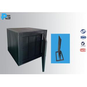
IEC60598-1 Annex Double-layer Draught-Proof Enclosure Made by Perforated Metal
1. Introduction
Draught-proof enclosure is designed according to IEC60598.1 annex
D. The size of draught-proof enclosure can be customized. It is applied to thermal test of luminaire under the conditions of
normal operation and abnormal operation. The draught-proof
enclosure is rectangular, with a double skin on top and on at least
three side, and with a solid base. The double skins are of
perforated metal, spaced approximately 150mm apart, with regular
perforations of 1mm to 2mm diameter, occupying about 40% of the
whole area of each skin. At the top of enclosure shall mounted a
ceiling plate or a dismountable hanging bracket with a hook to fix
the luminaire at the ceiling. At the bottom of side of enclosure
shall install inlet hole for the purpose of wire connection. For
the sake of install luminaire, the enclosure equip with a sample
holder, as per the standard, 2-layer black solid-board is applied
to fix the luminaire under test.
2. Specification
| outer shell structure | double layer rectangular structure, made by 1mm cold steel plate (black matt paint) |
| Outer size | 2100*2100*2150mm (customizable) |
| Inner size | 1800*1800*2000mm (customizable) |
| Spaced interval | 150mm |
| Door structure | single, double layer (outward open), 1800mm*800mm |
| Aperture | ф1mm -ф2mm |
| Ventilation rate | 40%±0.5% |
| Frame type | Sheet material, impact molding, not affect ventilation rate |
| Surface coating | black matt paint |
| plywood with matt paint size | 2500mm*2500mm*15mm (L*W*Thickness) |
| Ceiling mounting board | 600mm*600mm (L*W), coating with black matt paint |
| Installation plate | 0.6~1.0m (height, adjustable), composite board with black matt paint, enable vertical or horizontal install luminaire, wooden table: 600*500mm, adopts aluminium lifting. |
| Thermal slices | Φ15X1,latten |
3. Third-Lab Calibration Certificate
The following recommendations refer to the construction and use of a suitable draught-proof enclosure for luminaires, as required for the tests of normal and abnormal operation. Alternative constructions for draught-proof enclosures are suitable if it is established that similar results are obtained.
1. The draught-proof enclosure is rectangular, with a double skin
on top and on at least three sides, and with a solid base. The
double skins are of perforated metal, spaced approximately 150 mm
apart, with regular perforations of 1 mm to 2 mm diameter,
occupying about 40 % of the whole area of each skin.
2. The internal surfaces are painted with a matt paint. The three
principal internal dimensions are each at least 900 mm. There shall
be a clearance of at least 200 mm between the internal surfaces and
any part of the largest luminaire for which the enclosure is
designed.
NOTE: If it is required to test two or more luminaires in a large
enclosure, care should be taken that radiation from one luminaire
cannot affect any other.
3. There is a clearance of at least 300 mm above the top of the enclosure and around the perforated sides. The enclosure is at a location protected as far as possible from draughts and sudden changes in air temperature; it is also protected from sources of radiant heat.
4. A luminaire under test is positioned as far away as possible
from the six internal surfaces of the enclosure. The luminaire is
mounted (subject to the requirements of 12.4.1 and 12.5.1) as under
service conditions.
5. A luminaire for direct fixing to a ceiling or wall should be
fixed to a mounting surface comprising a wood or wood-fibre board.
A non-combustible insulating material is used if the luminaire is
not suitable for mounting on a combustible surface. The board is 15
mm to 20 mm thick, and extends not less than 100 mm (but preferably
not more than 200 mm) beyond the normal projection of the smoothed
outline of the luminaire. There is a clearance of at least 100 mm
between the board and the internal surfaces of the enclosure. The
board is painted black with a matt non-metallic paint.
A luminaire for corner-fixing is fixed in a corner comprising two
boards, each complying with the preceding requirements.
A third board is required if the luminaire is to be fixed in a
vertical corner immediately below a simulated ceiling.
Luminaires shall not cause the recess to attain temperatures likely
to cause a hazard or fire risk and compliance is checked by the
following test.
Recessed luminaires are mounted in a test recess, consisting of a
suspended ceiling, on top of which is a rectangular box with
vertical sides and horizontal top.
The suspended ceiling is made of a 12 mm thick porous wood-fibre
board, in which a suitable opening has been made for the luminaire.
The wood-fibre board shall extend at least 100 mm outside the
projection of the luminaire on this board. The vertical sides of
the box are made of 19 mm thick laminated wood and the top of 12 mm
thick porous wood-fibre board tightly sealed to the sides.
a) Luminaires for recessing into ceilings with thermal insulating
material covering the
Luminaire Sealed box with thermal insulating material tightly
fitted to the outside of the box. The thermal insulation shall be
equivalent to two 10 cm thick layers of mineral wool with a
coefficient of thermal resistivity of 0,04 W/(m.K). Thinner layers
can be used when having a higher thermal resistivity. The thermal
resistance of the test box shall in any case be at least 5 m2 K/W.
b) Luminaires for recessing into ceilings but not suitable for
covering with thermal insulating material
For recessed luminaires of this kind, the test recess shall be of
the same materials as described above.
The sides and top of the box shall be spaced from the luminaire in
accordance with the manufacturer’s instructions supplied with the
luminaire. If no spacing is specified, the sealed box shall touch
the luminaire all around.
If a luminaire is provided with separate parts intended for
recessed mounting, (for example, with separate lamp enclosure and
control gear enclosure), the test recess shall be constructed as a
single box observing the manufacturers recommendations for minimum
spacing between parts and the inside of the recess (see Figure
D.1). Where spacing between parts is not specified (item a of
Figure D.1), separate test recesses shall be used for each part.

