
Add to Cart
High Power Stationary RCIED Bomb Jammer, High Power DDS Jammer, Full Band Wireless Signal Jammer
User Manual - > Remote Controlled Improvised Explosive Device Jamm...
Product Instruchtion
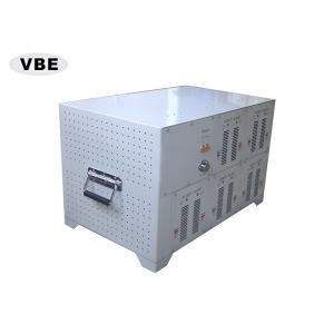
Now let us introduce this mobile signal jammer to you and give you better understanding of the positions of all the buttons, functions of accessories and other hardware.
Control Panel
Tag:Front Panel View
Tag: Back Panel View
Tag: RF POWER SWITCH
Press the green light button to activate corresponding power amplifier
Tag: Warning LED
Red Light With VSWR Warning
Tag: Each is 31dB adjustable output power adjustable step is 1dB
Product Technique characteristics
Product Parameter specifications
| Channel | Center Frequency | Frequency Range | Band Width | Output Power | Channel Output Power |
| CH1 | 54MHz | 20-88MHz | 68MHz | 50dBm | 19dBm/30KHz(min) |
| CH2 | 1842.5MHz | 1805-1880MHz | 75MHz | 51.3dBm | 18dBm/30KHz(min) |
| CH3 | 121.5MHz | 88-155MHz | 67MHz | 50dBm | 19dBm/30KHz(min) |
| CH4 | 1960MHz | 1930-1990MHz | 60MHz | 51.3dBm | 19dBm/30KHz(min) |
| CH5 | 375MHz | 300-450MHz | 150MHz | 50dBm | 20dBm/30KHz(min) |
| CH6 | 2441.75MHz | 2400-2483.5MHz | 83.5MHz | 50dBm | 18dBm/30KHz(min) |
| CH7 | 872.5MHz | 851-894MHz | 43MHz | 51.3dBm | 20dBm/30KHz(min) |
| CH8 | 942.5MHz | 925-960MHz | 35MHz | 51.3dBm | 22dBm/30KHz(min) |
| CH9 | 1575.42MHz | 1570.42-1580.42MHz | 5MHz | 50dBm | 18dBm/30KHz(min) |
| CH10 | 2135MHz | 2100-2170MHz | 60MHz | 51.3dBm | 20dBm/30KHz(min) |
| Power Supply:AC 220V Shielding area:100-500M @ according to signal density mobile | |||||
| Power consumption:3000 W Weight:64.5 Kg Side(length×wide×high): 640x400x400 mm | |||||
System fittings
System fittings consist of block package, panel antenna, antenna connecter lines (cable and N connecters) etc. 10 modules are responsible respectively for CDMA, GSM, DCS,WiFi,WLAN, which controls adjustment of output power, power switcher, as well as kinds of alarms( over heating and VSWR) . The next step will provide the function of each fitting in brief.
Anntenna
The jammer you bought is made up of jammer and antennas. It contains 10 modules(CH1~CH10).Each module can adjust power, warning standing wave indicator and warning temperature indicator separately.
Frequency: 20~88MHz,88~155MHz,300~450MHz ( total 3pcs ).
Gain : 3dbi.
Connector type : N type
Photo:
Vertical Ichnography:
| Frequency Range | 20~88MHz | 88~155MHz | 300~450MHz |
| Model | TQJ-100-3 | TQJ-150-3 | TQJ-300/400-3 |
| Input Impedance | 50Ω | ||
| VSWR | ≤1.8 | ||
| Gain | 3dBi | ||
| Maximum Power | 150W | ||
| Polarization | Vertical Polarization | ||
| PIM | <-107dBm | ||
| Connector Type | 7/16 or N-K | ||
| Lighting Protection | Direct Ground | ||
| Wind Velocity | 60(m/s) | ||
| Hold Pole Diameter | φ40(mm) | ||
Frequency:925~960MHz/1805~1880MHz,851~894/2110-2170MHz,1570.42~1580.42/2400~2483.5MHz,1930~1990MHz ( total 7pcs )
Gain:12-15dbi
Interface: N type
Photo:
Vertical Ichnography:
| Frequency Range | 851~894 MHz | 925~960 MHz | 1570.42~1580.42 MHz | 1805~1880 MHz | 1930~1990 MHz | 2110~2170 MHz | 2400~2483.5 MHz |
| Model | ANT-800-2500-12 | ||||||
| Input Impedance | 50Ω | ||||||
| VSWR | ≤1.8 | ||||||
| Gain | 12dBi | ||||||
| Maximum Power | 150W | ||||||
| Polarization | Vertical Polarization | ||||||
| PIM | <-107dBm | ||||||
| Connector Type | 7/16 or N-K | ||||||
| Lighting Protection | Direct Ground | ||||||
| Wind Velocity | 60(m/s) | ||||||
| Hold Pole Diameter | φ40(mm) | ||||||
Connecter line
Using Guide
Step 1: opens the box
Step 2: connecting cables and antennas
Step 3: Start shield
Step4: Turn off the shield