
Add to Cart
Automatic Or Semi-automatic SS CIP System Auxiliary Brewing Equipments For Beer Brewing Processing
CIP Product description
Clean-in-Place (CIP) is a method of cleaning the interior surfaces of pipes, vessels, process equipment, without disassembly. The benefit to industries that use CIP is that the cleaning is faster, less labor-intensive and more repeatable, and poses less of a chemical exposure risk to people. Manual CIP skids have a balance tank, centrifugal pump, and connection to the system being cleaned. Fixed CIP stations include fully automated systems with PLC, multiple balance tanks, sensors, valves, heat exchangers, data acquisition and Spray balls. The Steam-In-Place (SIP) System is responsible for repeatedly steaming areas of product contact to reduce the bio-burden on the system. The steam system must be able to measure and control steam temperature, pressure, and/or flow to ensure adequate steaming.
Applications
Fermenters, Vessels, Storage Tanks
Bioreactors, Mixers, Silos
Buffer preparation hold systems
Formulation systems
Closed loop Equipment & piping systems, viz Process Piping, Heat exchangers, Boilers, Pasteurizers, etc
CIP Design Concept
Each equipment is designed (in single or multi-tank configuration) to achieve the most effective and easily available cleaning systems, starting from:
Type, size & location of equipment to be washed
Required type of water and chemical agent
Soiling levels of the product to be removed
CIP Supply & Return pump requirements
Cleaning Spray Balls/nozzles type
Washing sequence, automation level
Heating arrangements
CIP Technical Parameters
In CIP/SIP automatic stations, CIP critical parameters integrated are:
Contact time of solution
CIP Supply & Return temperature
Chemical conductivity for wash solutions
CIP solution flow rate & pressure
Tanks levels
Above parameters can be constantly monitored by the PLC and managed with cost-savings criteria. CIP/SIP System can be customized with different washing cycle programs.
Model | Capacity(t/h) | External dimension(L*W*H) (mm) | Ice water consumption | Suggested power(kw) |
Kcal | ||||
YCIP-2 | 2 | 1100*1200*2800 | ≤1 | 5.5 |
YCIP-3 | 3 | 1100*1200*2800 | ≤1.5 | 6 |
YCIP-5 | 5 | 1100*1200*3000 | ≤2.5 | 7.5 |
YCIP-6 | 6 | 1200*1400*3500 | ≤3 | 9 |
YCIP-8 | 8 | 1400*1700*4000 | ≤4 | 12 |
YCIP-10 | 10 | 1400*1700*4000 | ≤5 | 15 |
YCIP-12 | 12 | 1600*2000*4200 | ≤6 | 22 |
YCIP-15 | 15 | 1700*2200*4200 | ≤7 | 22 |
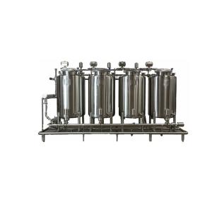
CIP Specifications --consists of the following elements:
1. Two SS 316 tanks, one jacketed (with Rockwool insulation) or 1000L for the preparation of caustic solution with conical bottom & another tank of 1000L non-jacketed for preparation of the Acid solution. Both fitted with fixed spray balls for self-cleaning of tanks.
2. One SS 304 tank, jacketed 1500L for recovered water with a conical bottom. Fitted with static spray ball.
3. Heating carried out by a Tubular steam heat exchanger, with a Pneumatic steam control valve, drains & Steam condensate valve.
4. Air operated double diagram pumps (MOC-PP/PTFE) for concentrate chemical dosing.
5. 5.5 kW, SS 316L with Mech. Seal-C/SiC & EPDM seals, CIP Supply pump with VFD & 5.5 kW self-priming pump for CIP return. Both pumps fitted with SS 304 Shrouds.
6. Pneumatic butterfly valves, SS 316L with actuators w/o feedback
7. SS 304 Skid with adjustable level pads.
8. Level control in the tanks.
9. A flow switch, Temperature & Conductivity controller, Inline Strainer (0.5 mm screen) & Sampling valve mounted in the CIP return line.
10. Flow & Pressure transmitter, Temperature controller, Heat exchanger, Pressure gauge mounted on the CIP supply line.
11. SS 304 Control cabinet with 10" touch screen Allen Bradley HMI & PLC control system.
12. 5 program preparation: Short tank cleaning, short line cleaning, tank long cleaning and long line cleaning, Manual valve activation. Plant state displaying, Change of parameters.
13. Pickled and passivated internal weld joints. Surface finish – Mirror up to 240 grit/ Matt up to 180 grit as per requirements.
CIP Display


