
Add to Cart
DC48V Rack Mount Rectifier High-Capacity M45D65B 220VAC Single Phase
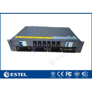
1. Rack Mount Rectifier Overview
M45D65B is a 19-inch sub-rack for hybrid power system , with 2U height compact design to meet critical application needs of fiber and microwave transmission, access device, switch.
The system’s maximum power is 90A, with AC input/DC input/battery/load MCBs. The cables are front accessing with MCB and busbar. This power system supplies power to -48V communication
Equipment.
2. System Parameter
| Category | M45D65B | |
| System | Dimension(mm) | 482.0(W)*350.0(D)*2U(H) |
| Weight | ≤15kg(without rectifier module) | |
| Cooling mode | Natural cooling | |
| Installation mode | Installed on 19-inch rack or inside the cabinet | |
| IP Grade | IP20 | |
| AC Distribution | Input Voltage | 220VAC single phase |
| Input capacity | 1×50A/2P;MCB:C63A/2P | |
| Input frequency | 45~66Hz, rated 50/60Hz | |
| AC SPD | 20kA/40kA, 8/20μs | |
| DC Distribution | Output voltage | -42~-58VDC,rated value:-53.5VDC |
| Maximum capacity | 4.2kW(3*3000W rectifier module) | |
| Battery connection | 2×85A/2P;MCB:C63A/1P*2 | |
| Load breakers | 6×50A/2P | |
| DC SPD | 10kA/, 8/20μs | |
| Rectifier module | Efficiency | ≥96% |
| Rated power | 1740W(176~300VAC) | |
| Working temperature | -40℃~+75℃(fully output below 50℃) | |
| Dimension | 105.5mm(W)×286mm(D)×41.5mm(1U/H) | |
| Cooling mode | Forced cooling with fan | |
| Controller | Signal input | 4 AI(3 Battery temp., 1 ambient temp) ,6 DI(SPD, 6 common DI) |
| Alarm output | 4 dry contact | |
| Communication port | LAN/RS232/RS485 interface,LAN-SNMP,TCP/IP | |
| Display mode | LCD | |
| Environment | Operating temperature | -40℃~+65℃ |
| Storage temperature | -40℃~+70℃ | |
| Operating humidity | 0%~95%(non-condensing) | |
| Altitude | 0~3000m(If the altitude is within the range of 2000m to 3000m, the maximum operating temperature decreases by 1℃ as the altitude increases by 200m.) | |
3. Telecom Rectifier Quick Details
4. Working Principles
(1) AC input: Startup rectifier module after AC powered-on, outputs -48Vdc, at the same time charge the battery and power the conversion module, conversion module outputs 220Vac.
Under normal conditions, the parameters of rectifier module and distribution unit are all under controll of the monitoring module, operating according to the preset parameters or user’s commands. If AC mains fault,
the battery will power to the system, and continue outputing - 48 VDC and 220 vac, with the discharge of the battery, the voltage of the battery starts to descend, when the voltage is under 43.2 V + / - 0.5 V,
the monitoring module send battery under-voltage signal and close the load output directly, then the power system will stop working. When external AC mains recovers,
the system will normally work again. (All above monitoring data are system default values and can be reset by user)
(2) -48V input: No AC current or no AC be connected, access external power -48V to -48V load port, startup monitoring and conversion module, 220Vac output.
Figure Conceptual diagram
5. Rectifier module
The module panel
(1) Power indicator
(2) Alarm indicator
(3) Fault indicator
(4) Locking latch
(5) Handle
There are three indicator on the panel,which are used to reflect the operation status of the rectifier,see Table below for details.
Table Rectifier indicator description
| Indicator | Color | Status | Reasons for abnormal status |
| Power indicator | Green | Normally on | The module has and power input |
| Off | Main supply fault(no power input or OVP,UVP of power input).non-output | ||
| Alarm indicator | Yellow | Normally on | Temperature alarm(OTP when the ambient temperature>65℃) |
| The module is hibernating. (indicator lighting, no alarm) | |||
| The module is current-limiting | |||
| Flickering | Communication failure | ||
Fault indicator | Red | Normally on | Non-output caused by module inner reason such as OVP, fan fault, OTP |
| Normally off | The module is running properly. |
6. Controller-MC2600
The MC2600 front panel
Table for controller button description
| Button | Description | |
| ESC | Returns to the previous menu without saving the settings. | Press the ESC and ENT button at the same time within a short period of time can restart the controller. |
ENT. | Ø Enters the main menu from the standby screen. Ø Enters a submenu from the main menu. Ø Saves the menu settings. | |
| UP | Turns to the previous menu or sets parameter values. When setting parameter values, you can hold down this button to quickly adjust values. | When the parameter value is set by multiple string types, press up or down button to change each value. After setting the value, press the confirm button to move the cursor back automatically. |
| DN. | Turns to the next menu or sets parameter values. When setting parameter values, you can hold down this button to quickly adjust values. | |
Describes the indicator on the controller panel is shown in table below
| Type | Color | State | Instructions |
| Run indicator | Green | Flickering | Controller is running properly |
| Off | Controller is fault or has no DC input | ||
| Minor Alarm | Yellow | Normally on | The controller generates a minor alarm |
| Off | The controller does not generate any minor alarms | ||
| Major alarm | Red | Normally on | The controller generates a major alarm |
| Off | The controller does not generate any major alarms |
The controller provides two communication ports,
The definition of RS485 communication port is shown in below table
| Pin No. | 1 | 2 | 3 | 4 | 5 | 6 | 7 | 8 |
| Signal name | RS485+ | - | RS485- | - | - | - | - | - |
The LAN Ethernet port interface definition is shown in Table
| Pin No. | 1 | 2 | 3 | 4 | 5 | 6 | 7 | 8 |
| Signal name | TX+ | TX- | RX+ | - | - | RX- | - | - |
7. DI/DO Interface
The DI/DO interface board front panel
Digital input is submenu of parameter setting menu, which is mainly used for the operator to configure the input normal state of 8 digital switches in the system.
Table Relay input parameter setting
| Digital No. | Digital name | DI Normal | Description |
| DI1 | HEX Alarm | NO | It is normal when opened; and the alarm occurs when closed. |
| DI2 | PWC Door Alarm | NC | It is normal when opened; and the alarm occurs when closed. |
| DI3 | BT Alarm | NO | It is normal when opened; and the alarm occurs when closed. |
| DI4 | BC Alarm | NO | It is normal when opened; and the alarm occurs when closed. |
| DI5 | Digital5 Alarm | NO | It is normal when opened; and the alarm occurs when closed. |
| DI6 | Genset on Alarm | NO | It is normal when opened; and the alarm occurs when closed. |
| DI7 | DC SPD Alarm | NC | It is normal when opened; and the alarm occurs when closed. |
Relay output is submenu of parameter setting menu, which is mainly used for the operator to configure the output normal state of 8 relays in the system.
Table Relay output parameter setting
| Digital No. | Digital Name | Alarm code | Description |
| DO1 | Relay output 1 | NC | Closed when normal,opened when associated alarm occurs. |
| DO2 | Relay output 2 | NC | Closed when normal,opened when associated alarm occurs. |
| DO3 | Relay output 3 | NC | Closed when normal,opened when associated alarm occurs. |
| DO4 | Relay output 4 | NC | Closed when normal,opened when associated alarm occurs. |
| DO5 | Relay output 5 | NC | Closed when normal,opened when associated alarm occurs. |
| DO6 | Relay output 6 | NC | Closed when normal,opened when associated alarm occurs. |
| DO7 | Relay output 7 | NC | Closed when normal,opened when associated alarm occurs. |
In addition, the product provides 6 other ports.
Table Other intput parameter setting
| Parameter name | Setting description |
| BTEMP 1 | Battery sensor1 port |
| BTEMP 2 | Battery sensor2 port |
| ENV_TEMP | Enveropment sensor port |
| 12V +/- | 12V power supply is provided |
| RS485 | RS485 port, reserved interface, no protocol definition |
| OIL+/- | Connect the oil level sensor |
Wiring methods:
Ø Remove the cable insulation with wire stripping pliers. The exposed length of the cable core shall not be less than 10 mm.
Ø Press the button above the terminal with the screwdriver, insert the cable, release the screwdriver and complete the cable connection.
Ø With handle gently pull cables, to ensure that the cable does not fall off.
8. Installing Subrack
Install the subrack to the 19-inch rack, as shown in Figure below.
Ø Step 1,Remove the plug from the package.
Ø Step 2,Push the plug into the 19-inch rack
Ø Step 3,Install the fixed screw (if the mounting hole of the plug frame ear does not correspond to the position of the floating nut of the frame, it needs to be adjusted according to the actual installation).
Install Rectifier module
Ø Step 1,Take out the module from the package.
Ø Step 2,Hold the module handle on the front panel and put the module onto the slot.
Ø Step 3,Push the module module slowly to the front panel of the module and flush with the power
distribution panel.
Ø Step 4,Tighten the fixing screw on the module panel so that the module does not come off.
9. Packing and Shipping
Package use free fumigation woodcase which is suitable for export. This package is anti moisture, anti impact and srong to ensure safe transportation.