UL 310 Table 3 ( Ninth Edition ) Test Tab For Safety For Electrical Quick - Connect Terminals
Brand Name:Kingpo
Certification:Calibration Certificate
Minimum Order Quantity:1
Delivery Time:goods in stock
Payment Terms:T/T
Place of Origin:China
Contact Now
Add to Cart
Verified Supplier
Location:
Hong kong Hong kong China
Address:
RM C, 13/F, HARVARD COMMERCIAL BUILDING, 105-111 THOMSON ROAD, WAN CHAI, HK
Supplier`s last login times:
within 11 hours
Product Details
Company Profile
Product Details
UL Standard for Safety for Electrical Quick-Connect Terminals,
UL 310
Ninth Edition
5.2.2 Test tab
5.2.2.1 Test tabs for the insertion-withdrawal test described in
Clause 6.4 shall be made of unplated brass, identified as CDA C26000 Alloy
with a hardness of 62 ±7 on the Rockwell 30T scale.
5.2.2.2 Test tabs for the temperature and current cycling tests
described in Clause 6.5 shall be made of tin-plated steel or corrosion resistant steel
having a hardness of 68 ±5 on the Rockwell 30T scale.
5.2.2.3 In regard to Clause 5.2.2.2, for connectors intended exclusively for use with production tabs
of copper alloy, an unplated brass test tab of C26000 Alloy with a
hardness of 62 ±7 on the Rockwell 30T scale may be used.
5.3.3 Test tab
5.3.3.1 Single-ended test tabs for the insertion-withdrawal test
shall have the configuration shown in Figures 2 to 4 and the dimensions specified in Tables 2 and 3. The "C" dimension tolerance shall be ±0.008 mm (0.0003 in) for
brass and ±0.013 mm (0.0005 in) for steel, and raised plateaus
around the detent shall be limited to a combined total of 0.03 mm
(0.001 in) for both sides.
5.3.3.2 Double-ended test tabs for the temperature and current
cycling tests shall be constructed in accordance with Clause 5.3.3.1 and have the configuration shown in Figure 5.
Table 3
Dimensions of metric production and test tabs in millimeters
(See note to Figure 5)
| Nominal size | A | B(min) | C | D | E | F | J | M | N | P | Q(min) |
| 2.8 x 0.5 with dimple | 0.6 | 7.0 | 0.54 | 2.90 | 1.8 | 1.3 | 12° | 1.7 | 1.4 | 1.4 | 8.1 |
| 0.3 | 0.47 | 2.70 | 1.3 | 1.1 | 8° | 1.4 | 1.0 | 0.3 | |||
| 2.8 x 0.5 with hole | 0.6 | 7.0 | 0.54 | 2.90 | 1.8 | 1.3 | 12° | 1.4 | 8.1 | ||
| 0.3 | 0.47 | 2.70 | 1.3 | 1.1 | 8° | 0.3 | |||||
| 2.8 x 0.8 with dimple | 0.6 | 7.0 | 0.84 | 2.90 | 1.8 | 1.3 | 12° | 1.7 | 1.4 | 1.4 | 8.1 |
| 0.3 | 0.77 | 2.70 | 1.3 | 1.1 | 8° | 1.4 | 1.0 | 0.3 | |||
| 2.8 x 0.8 with hole | 0.6 | 7.0 | 0.84 | 2.90 | 1.8 | 1.3 | 12° | 1.4 | 8.1 | ||
| 0.3 | 0.77 | 2.70 | 1.3 | 1.1 | 8° | 0.3 | |||||
| 3.2 x 0.8 with dimple | 0.6 | 7.0 | 0.84 | 3.25 | 1.8 | 1.3 | 12° | 1.7 | 1.4 | 1.4 | 8.1 |
| 0.3 | 0.79 | 3.10 | 1.4 | 1.1 | 8° | 1.4 | 1.1 | 0.3 | |||
| 3.2 x 0.8 with hole | 0.6 | 7.0 | 0.84 | 3.25 | 1.8 | 1.3 | 12° | 1.4 | 8.1 | ||
| 0.3 | 0.79 | 3.10 | 1.4 | 1.1 | 8° | 0.3 | |||||
| 3.2 x 0.5 with dimple | 0.6 | 7.0 | 0.54 | 3.25 | 1.8 | 1.3 | 12° | 1.7 | 1.4 | 1.4 | 8.1 |
| 0.3 | 0.48 | 3.10 | 1.4 | 1.1 | 8° | 1.4 | 1.1 | 0.3 | |||
| 3.2 x 0.5 with hole | 0.6 | 7.0 | 0.54 | 3.25 | 1.8 | 1.3 | 12° | 1.4 | 8.1 | ||
| 0.3 | 0.48 | 3.10 | 1.4 | 1.1 | 8° | 0.3 | |||||
| 4.8 x 0.5 with dimple | 0.9 | 6.2 | 0.54 | 4.80 | 2.8 | 1.5 | 12° | 1.7 | 1.5 | 1.7 | 7.3 |
| 0.6 | 0.47 | 4.60 | 2.3 | 1.3 | 8° | 1.4 | 1.2 | 0.6 | |||
| 4.8 x 0.5 with hole | 0.9 | 6.2 | 0.54 | 4.90 | 3.4 | 1.5 | 12° | 1.7 | 7.3 | ||
| 0.6 | 0.47 | 4.67 | 3.0 | 1.3 | 8° | 0.6 | |||||
| 4.8 x 0.8 with dimple | 1.0 | 6.2 | 0.84 | 4.80 | 2.8 | 1.5 | 12° | 1.7 | 1.5 | 1.8 | 7.3 |
| 0.7 | 0.77 | 4.60 | 2.3 | 1.3 | 8° | 1.4 | 1.2 | 0.7 | |||
| 4.8 x 0.8 with hole | 1.0 | 6.2 | 0.84 | 4.90 | 3.4 | 1.5 | 12° | 1.8 | 7.3 | ||
| 0.6 | 0.77 | 4.67 | 3.0 | 1.3 | 8° | 0.7 | |||||
| 5.2 x 0.5 with dimple | 1.0 | 6.2 | 0.54 | 5.30 | 2.8 | 1.9 | 12° | 2.5 | 2.0 | 1.7 | 7.3 |
| 0.7 | 0.47 | 5.10 | 2.3 | 1.6 | 8° | 2.2 | 1.8 | 0.6 | |||
| 5.2 x 0.5 with hole | 1.0 | 6.2 | 0.54 | 5.30 | 3.4 | 1.9 | 12° | 1.7 | 7.3 | ||
| 0.7 | 0.47 | 5.10 | 3.0 | 1.6 | 8° | 0.6 | |||||
| 5.2 x 0.8 with dimple | 1.0 | 6.2 | 0.84 | 5.30 | 2.8 | 1.9 | 12° | 2.5 | 2.0 | 1.8 | 7.3 |
| 0.7 | 0.77 | 5.10 | 2.3 | 1.6 | 8° | 2.2 | 1.8 | 0.7 | |||
| 5.2 x 0.8 with hole | 1.0 | 6.2 | 0.84 | 5.30 | 3.4 | 1.9 | 12° | 1.8 | 7.3 | ||
| 0.7 | 0.77 | 5.10 | 3.0 | 1.6 | 8° | 0.7 | |||||
| 6.3 x 0.8 with dimple | 1.0 | 7.8 | 0.84 | 6.40 | 4.1 | 2.0 | 12° | 2.5 | 2.0 | 1.8 | 8.9 |
| 0.7 | 0.77 | 6.20 | 3.6 | 1.6 | 8° | 2.2 | 1.8 | 0.7 | |||
| 6.3 x 0.8 with hole | 1.0 | 7.8 | 0.84 | 6.40 | 4.7 | 2.0 | 12° | 1.8 | 8.9 | ||
| 0.5 | 0.77 | 6.20 | 4.3 | 1.6 | 8° | 0.7 | |||||
| Notes: 1. Included are dimensions for those nominal sizes corresponding with those found in IEC 61210. 2. In the table where two values are provided, the lesser value is the minimum permitted value and the larger is the maximum permitted value. | |||||||||||
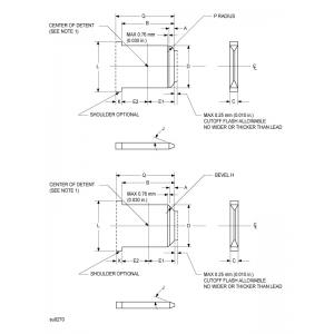
Figure 2
Dimensions of production and test tabs
Note 1 - For dimple and hole detent dimensions F, G, M, and N, see Figures 3 and 4.
Note 2 - Bevel "H" need not be a straight line if it is within the confines shown, and it may be a radius of "P".
Note 3 - "Q" dimension is for tabs without shoulders.
Note 4 - "L" dimension not specified.
Figure 3
Dimensions of dimple detents
Figure 4
Dimensions of hole detents
Figure 5
Double-ended test tab for temperature rise and heat cycling tests
Note: See Figures 2 to 4 and Table 2 or 3.
Figure 6
Connection and arrangement for temperature and current cycling tests


UL 310 Table 3 ( Ninth Edition ) Test Tab For Safety For Electrical Quick - Connect Terminals
Inquiry Cart
0