Add to Cart
GPU PCI Express 1X To 1X / 4x / 8x / X16 Riser Card Extender With Magnetic Foot Pads.
Specification:
1,Supports high speed PCI-E1x/4x/8x/ 16X card.
2,Dustproof cap and golden finger protection cover design.
3,With 3x solid capacitors, making sure power supply more stable and secure.
4,Experienced design and durable material for High frequency and low attenuation.
5,USB 3.0 cable length: 58cm.
6,12v, 5v and3.3v LED indicator design.
7,Magnetic foot pad design for more secure and reliable installation.
Product Overview:
This product is a unique PCI-E 1X to PCI-E 1X USB 3.0 extension
cable, consisting of two independent PCB boards, designed to solve
the connection and extension transmission problems between PCI-E
devices and USB 3.0 interfaces for users, while providing many
practical functions and convenient designs. It can not only achieve
the conversion and connection between PCI-E devices with different
bandwidths and USB3.0, but also be easily fixed in the chassis
through magnetic foot pads. It is equipped with a small 4PIN
auxiliary power supply interface that can be converted to SATA for
powering PCI-E devices, which is widely used in computer hardware
expansion, chassis internal wiring optimization, and various
application scenarios that require high flexibility in device
connection.
Name | Alternative Name | USB-IF Trademark | Bit Rate | Introduction |
| USB 1.1 | Low - Speed (LS) | 1.5Mb/sec. | 1996 | |
| Full-Speed(FS) | 12Mb/sec. | 1996 | ||
| USB 2.0 | High-Speed (HS) | 480Mb/sec | 2000 | |
| USB 3.0 | Super-Speed (ss) | 5.0Gb/sec | 2008 |
Product features:
1. Flexible PCI-E device compatibility: PCB boards with PCI-E 1X slots demonstrate excellent compatibility
and can support devices with different bandwidths such as PCI-E 1X,
PCI-E 4X, PCI-E 8X, and PCI-E 16X. Whether users are connecting
small expansion cards with relatively low bandwidth requirements or
high-performance devices with high bandwidth requirements, stable
connections can be achieved through this slot, fully leveraging the
performance advantages of the devices, providing users with great
flexibility in selecting and matching PCI-E devices, meeting
diverse hardware expansion needs, and enabling different types of
devices to be integrated into corresponding computer systems.
2. Convenient USB 3.0 extension transfer: The product cleverly connects the PCI-E slot to the USB 3.0
interface through two independent PCB boards, and uses a USB 3.0
extension cable to achieve data transfer. This design breaks the
spatial limitations of traditional connection methods. Users can
flexibly adjust the position of two PCB boards according to the
actual layout and usage needs inside the chassis, conveniently
extending the distance between PCI-E devices and other devices
(such as computer hosts), optimizing the internal wiring of the
chassis, avoiding connection difficulties caused by distance
issues, and ensuring stable and efficient data transmission of USB
3.0 interface, meeting the data transmission needs of external
storage devices, USB interface expansion devices, etc.
3. Practical magnetic foot pad design: Three magnetic foot pads are equipped under the PCB board with
PCI-E 1X slots, which greatly enhances the convenience of the
product during use. When the user places the PCB board inside the
chassis, the magnetic foot pad can easily adhere to the surface of
the chassis, firmly fixing the PCB board in the appropriate
position, avoiding PCB board displacement due to chassis vibration
or other external factors, ensuring the stability of the
connection, and also facilitating the user's disassembly and
reinstallation when adjusting the position, providing convenience
for hardware layout and maintenance inside the chassis.
4. Multi functional auxiliary power supply interface: The PCB board with slots also has a small 4PIN auxiliary power
supply interface, which has the function of converting to SATA,
providing reliable power supply for PCI-E devices. In some cases,
some PCI-E devices may have high requirements for power supply, or
when the motherboard power supply cannot meet the stable operation
needs of the device, this auxiliary power supply interface can play
an important role. By converting SATA power supply, it provides
additional power support for PCI-E devices, ensuring that the
device will not experience performance degradation, failure, or
other problems due to insufficient power supply during operation,
enhancing the stability and reliability of the entire hardware
system.
Product Structure and Interface Introduction:
PCI-E slot PCB board:
PCI-E 1X slot: Designed and manufactured strictly in accordance with the PCI-E
standard, the internal gold finger contact point layout is
reasonable, using high-quality conductive materials and finely
gold-plated, with excellent conductivity and oxidation resistance,
ensuring stable and reliable electrical connections between the
gold fingers of PCI-E devices with different bandwidths. The slot
is equipped with a stable fixed structure around it, which is fixed
by buckles or screws (depending on the device design) to ensure
that the device will not loosen or shift due to vibration,
collision, and other factors after insertion, ensuring the
stability of device operation and allowing the device to
continuously and stably exchange data with other devices under
long-term high load operation.
USB 3.0 interface: Following the USB 3.0 standard specification, the pin layout
inside the interface is precise, and high-quality metal materials
are used to create contact points with good conductivity and signal
transmission capabilities. It can achieve a tight and stable
connection with USB 3.0 extension cords, ensuring high-speed and
stable data transmission. At the same time, the external design of
the interface focuses on durability and ease of insertion and
extraction, making it convenient for users to plug and use multiple
times. Proper reinforcement treatment has been carried out around
the interface to prevent damage caused by external forces such as
pulling, ensuring the continuity of USB 3.0 data transmission.
Small 4PIN auxiliary power supply interface: designed according to the corresponding electrical specifications,
it has stable voltage output and suitable current carrying
capacity, and can provide additional power support for PCI-E
devices by converting to SATA. The pin definition of the interface
is clear, and it has good compatibility with the SATA power supply
line. Users only need to connect it according to the correct wiring
method to achieve the power supply function, ensuring that it can
meet the normal operation requirements of PCI-E devices in
different power supply demand scenarios.
PCI-E 1X Gold Finger PCB Board:
PCI-E 1X Gold Finger: It is also strictly built in accordance with the PCI-E 1X
standard, using high-quality alloy materials and fine processing
technology to ensure that the size accuracy and shape tolerance of
the gold finger meet the requirements. It can be accurately
inserted into the corresponding PCI-E 1X, PCI-E 4X, PCI-E 8X, and
PCI-E 16X slots on the motherboard (depending on the motherboard
support), achieving reliable electrical connections. The surface of
the golden finger has been specially treated to have good
conductivity and oxidation resistance, ensuring stable electrical
performance even after multiple insertions and long-term use,
providing a solid foundation for the entire hardware connection
system.
USB 3.0 interface: Consistent with the USB 3.0 interface specifications on the PCI-E
slot PCB board mentioned above, designed and manufactured strictly
in accordance with the USB 3.0 standard, with the same high-quality
contact points and stable signal transmission capabilities,
ensuring seamless connection with the USB 3.0 interface on the
other end through the USB 3.0 extension line, ensuring accurate and
fast data transmission between the two PCB boards, and meeting
users' data transmission needs for USB 3.0 interfaces, such as
connecting USB storage devices, USB docking stations, etc.
Transmission advantages:
USB 3.0 Stable and High Speed Transmission: With carefully designed USB 3.0 interfaces and high-quality USB
3.0 extension cables, the product can achieve stable and high-speed
data transmission. USB 3.0 itself has a high theoretical transfer
rate, which is sufficient to meet the needs of common application
scenarios such as large capacity file transfer (such as
high-definition videos, large software installation packages,
etc.), and data exchange with multiple devices connected
simultaneously (such as multiple USB storage devices reading and
writing data simultaneously). In practical use, by optimizing
internal circuit design and ensuring signal integrity, signal
attenuation and interference can be effectively reduced, ensuring
the integrity and accuracy of data during transmission, avoiding
problems such as transmission lag and packet loss, and providing
users with a smooth data transmission experience.
Adapt to different PCI-E devices for transmission: Due to the support for multiple bandwidth PCI-E device connections
and reliable electrical connection design and circuit optimization,
both low bandwidth PCI-E 1X devices and high bandwidth PCI-E 16X
devices can achieve stable data transmission through the adapter of
this product. When connecting different types of PCI-E devices,
such as graphics cards, sound cards, network cards, and other
expansion devices, the product can fully leverage its adaptability
advantages. According to the actual performance requirements of the
device, the corresponding bandwidth PCI-E channel is used for data
transmission, avoiding the impact of interface mismatch or
insufficient bandwidth on device performance, ensuring stable
operation of each device in the computer system, and meeting the
diverse hardware expansion needs of different users.
Usage:
Connecting PCI-E devices: First, carefully align the gold finger of the PCI-E device that
needs to be connected (such as an expansion card that meets the
bandwidth of PCI-E 1X, PCI-E 4X, PCI-E 8X, or PCI-E 16X) with the
slot on the PCB board with the PCI-E 1X slot. Pay attention to the
anti insertion error markings on the gold finger of the device and
the corresponding features of the slot to ensure correct
orientation. Then, smoothly insert the device into the slot until
it is fully inserted and firmly secured by the fixed structure of
the slot, avoiding damage to the device or slot caused by forced
insertion.
Connect USB 3.0 extension cable: Insert one end of the USB 3.0 extension cable into the USB 3.0
interface on a PCB board with a PCI-E 1X slot, ensuring that the
interface is fully inserted and securely connected. Then insert the
other end of the extension cable into the USB 3.0 interface on the
PCB board with a PCI-E 1X gold finger, ensuring that it is inserted
properly to avoid loosening. This establishes a data transmission
channel between the two PCB boards through the USB 3.0 extension
cable.
Fixed PCB board: Place the PCB board with PCI-E 1X slot and magnetic foot pad below
it in a suitable position inside the chassis, and use the suction
effect of the magnetic foot pad to firmly attach it to the surface
of the chassis, ensuring that it will not easily shift under
chassis vibration and other situations. For PCB boards with PCI-E
1X gold fingers, they can be inserted into the corresponding PCI-E
slots on the motherboard (such as PCI-E 1X, PCI-E 4X, PCI-E 8X, or
PCI-E 16X slots, with the motherboard supporting the corresponding
bandwidth) according to actual connection requirements, and ensure
that the insertion is firm. This can be confirmed by checking
whether the buckle is stuck or whether the screw is tightened.
Connecting auxiliary power supply (if necessary): If the connected PCI-E device has additional requirements for
power supply, or if unstable power supply is found during use, a
suitable power cord can be used to connect the small 4PIN auxiliary
power supply interface on the PCB board with slots to the SATA
power supply interface of the power supply through SATA conversion,
providing stable power supply for the PCI-E device and ensuring its
normal operation.
Applicable scenarios:
Computer hardware expansion and optimization layout: In the process of computer assembly or upgrade, when users need to
add PCI-E devices (such as high-performance network cards, sound
cards, etc.), but the internal space of the chassis is limited, the
connection distance between the device and the motherboard is
restricted, or they want to optimize the internal heat dissipation
and wiring of the chassis by adjusting the device position, the
USB3.0 extension line and magnetic foot pad design of this product
can play an important role. Users can flexibly place PCI-E devices
in suitable positions, achieve stable connections through extension
cords, and use magnetic foot pads to fix the PCB board, making the
hardware layout inside the chassis more reasonable and beautiful,
and improving the overall user experience.
Multi device connection and data sharing: For users who need to simultaneously connect multiple different
types of PCI-E devices and multiple USB interface devices, this
product provides a convenient solution. For example, on a computer,
a professional graphics card is connected for graphics processing
work, and multiple USB storage devices need to be connected for
data backup and sharing. Through the PCI-E to USB3.0 conversion
function and compatibility with different bandwidth PCI-E devices
of this product, it is easy to achieve simultaneous connection and
stable data interaction of multiple devices, meeting diverse work
and entertainment needs.
Solving the problem of insufficient power supply: Some high-performance PCI-E devices require high power supply
during operation, and sometimes the power provided by the
motherboard itself may not be able to meet their stable operation
needs. In this case, the function of converting the small 4PIN
auxiliary power supply interface to SATA that comes with this
product comes in handy. Users can provide additional power support
for the device through this interface, ensuring that the device
will not experience performance degradation, crashes, or other
issues due to insufficient power supply during high load operation
(such as large-scale game rendering, professional audio processing,
etc.), ensuring the normal use and performance of the device.
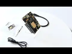
Package Contents:
1x 1X to 1X Riser Card.
1x USB 3.0 Cable.
1x SATA to 4 PIN power Cable.