
Add to Cart
Product advantages
1. Not affected by changes in fluid density, viscosity,
temperature, pressure and electrical rate, linear measurement
principle 2. Can achieve high-precision measurement;
3. There are no flow blocking parts in the measuring pipe, the
pressure loss is small, and the straight pipe section requirements
are low;
4. The nominal diameter covers a wide range from DN10 to DN2000,
and there are multiple options for linings and electrodes, which
can meet the requirements for measuring a variety of conductive
fluids;
5. The converter uses programmable frequency low-frequency
rectangular wave excitation, which improves the stability of flow
measurement and reduces power loss;
Pulse Output
Two types of pulse output are available to choose from: frequency
output mode and pulse output mode. The meter outputs continuous
square wave pulse under frequency mode, while pulse series under
pulse mode. Frequency output is usually used for flow rate
measurement and short period of time totalization. Pulse output can
be connected to an external counter directly and is often used for
long period of time totalization.
As mentioned hereinbefore, transistor open collector circuit is
used for frequency and pulse output. Therefore, the external DC
power supply and load are necessary.
Features
1. Measurement is not affected by the variation of flow density,
viscosity, temperature, pressure and conductivity. High accuracy
measurement is guaranteed according to the linear measurement
principle.
2. No obstacle in the pipe, no pressure-loss and lower requirement
for straight pipeline.
3. DN 6 to DN2000 covers a wide range of pipe size. A variety of
liners and electrodes are available to satisfy different flow
characteristic.
4. Programmable low frequency square wave field excitation,
improving measurement stability and reducing power consumption.
5. Implementing 16 bits MCU, providing high integration and
accuracy; Full-digital processing, high noise resistance and
reliable measurement; Flow measurement range up to 1500:1.
6. High definition LCD display with backlight.
7. RS485 or RS232 interface supports digital communication.
8. Intelligent empty pipe detection and electrodes resistance
measurement diagnosing empty pipe and electrodes contamination
accurately.
9. SMD component and surface mount technology (SMT) are implemented
to improve the reliability.
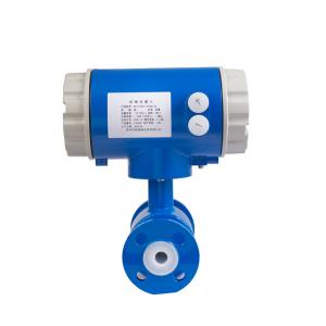
Main Applications
TQMF electromagnetic flowmeter can be used to measure the volume flow of conductive fluid in a closed pipeline. It is widely applied in the flow measurement and control in the fields of chemical and petroleum industry, metallurgy industry, water and waste water, agriculture and irrigation, paper making, food and beverage industry and pharmaceutical industry. 1.3Ambient Conditions Ambient temperature: sensor: -25℃ to + 60℃; converter: -25℃ to + 60℃. Relative humidity: 5% to 90%; 1.4Working Conditions Maximum fluid temperature: Compact type: 60℃ Remote type: Teflon 150℃ Neoprene 80℃; 120℃ Polyurethane 70℃ Fluid conductivity: ≥ 5S/cm
Measuring Principles
The measuring principle of electromagnetic flowmeter is based on the electromagnetic induction law of Farady. The sensor is mainly composed of measuring tube with isolate lining, a pair of electrodes installed by penetration of the measuring tube wall, a pair of coils and iron core to produce working magnetic field. When the conductive fluid flows through the measuring tube of the sensor, the voltage signal in direct proportion to the average flow velocity of the fluid will be inducted on the electrodes. The signal is amplified and treated by the transmitter to realize various display functions.
Converter Circuit Schematic
The converters supplies a stable exciting current to the coil in the sensor of electronetic flowmeters to get B constant and amplifies the electromotive force and convert it into standard signals of current or frequency so that the signals can be used for displaying, controlling and processing. The schematic of converter circuit is shown in Fig. 2.1.
Table of Parameter Setting Menu
The converter setting menu consists of 45 items. Many of them are set up by manufacturer before shipping. It is not necessary to change them when applying. There are only a few of them to be set by user according to the application. The menu items are listed in the table below:
| Item No. | Menu Display | Setting Method | Password Level | Value Range |
| 1 | Language | Option | 1 | Chinese/English |
| 2 | Sensor Size | Option | 1 | 3 - 3000mm |
| 3 | Flow Range | Modify | 1 | 0 - 99999 |
| 4 | Auto Rng Chg | Option | 1 | ON / OFF |
| 5 | Damping | Option | 1 | 0 - 100 s |
| 6 | Flow Dir. | Option | 1 | Fwd/ Res |
| 7 | Flow Zero | Modify | 1 | +/-0.000 |
| 8 | L.F. Cutoff | Modify | 1 | 0 - 99% |
| 9 | Cutoff Enble | Option | 1 | ON / OFF |
| 10 | Rate-Of-Chng | Modify | 1 | 0 - 30% |
| 11 | Limit Time | Modify | 1 | 0 - 20 s |
| 12 | Total Unit | Option | 1 | 0.0001L - 1 m3 |
| 13 | Flow Density | Modify | 1 | 0.0000 - 3.9999 |
| 14 | Current Type | Option | 1 | 4-20mA/0-10mA |
| 15 | Pulse Output | Option | 1 | Frq/ Pulse |
| 16 | Pulse Factor | Option | 1 | 0.001L - 1 m3 |
| 17 | Freq Max | Modify | 1 | 1 - 5999 Hz |
| 18 | Comm Address | Modify | 1 | 0 - 99 |
| 19 | Baudrate | Option | 1 | 600 - 14400 |
| 20 | EmpPipe Det. | Option | 1 | ON / OFF |
| 21 | EmpPipe Alm | Modify | 1 | 200.0 KΩ |
| 22 | Hi ALM Enble | Option | 1 | ON / OFF |
| 23 | Hi Alm Limit | Modify | 1 | 000.0 - 199.9% |
| 24 | Lo Alm Enble | Option | 1 | ON / OFF |
| 25 | Lo Alm Limit | Modify | 1 | 000.0 - 199.9% |
| 26 | RevMeas.Enbl | Option | 1 | ON/OFF |
| 27 | Sensor S/N | Modify | 2 | 000000000000-999999999999 |
| 28 | Sensor Fact. | Modify | 2 | 0.0000 - 3.9999 |
| 29 | Field Mode | Option | 2 | Mode 1,2,3 |
| 30 | Multiplying | Modify | 2 | 0.0000 - 3.9999 |
| 31 | F. Total Set | Modify | 3 | 0000000000 - 9999999999 |
| 32 | R.Total Set | Modify | 3 | 0000000000 - 9999999999 |
| 33 | Input Contrl | Option | 3 | Disable/Stop Tot/Reset Tot |
| 34 | Clr Totalizr | Password | 3 | 00000 - 59999 |
| 35 | Clr Tot. Key | Modify | 3 | 00000 - 59999 |
| 36 | Date –y/m/d * | Modify | 3 | 99/12/31 |
| 37 | Time-h/m/s * | Modify | 3 | 23/59/59 |
| 38 | Password L1 | Modify | 3 | 0000 - 9999 |
| 39 | Password L2 | Modify | 3 | 0000 - 9999 |
| 40 | Password L3 | Modify | 3 | 0000 - 9999 |
| 41 | Current Zero | Modify | 4 | 0.0000 - 1.9999 |
| 42 | Current Max | Modify | 4 | 0.0000 - 3.9999 |
| 43 | Meter Factor | Modify | 4 | 0.0000 - 3.9999 |
| 44 | Convtr S/N | Modify | 4 | 0000000000-9999999999 |
| 45 | Sys Reset | Password | 4 |
Scenario application:
FAQ
1. Q: What information need to be provided to choose the suitable
model?
A: Application field, Nominal pressure ,Medium & medium
temperture , Power supply , Output,
Flow range, Accuracy, Connection and other parameters.
2. Q: Are you a trade company or a manufacturer?
A: We are an ISO approved manufacturer specialized in level and
flow measuring instruments.
OEM & ODM service are available. Welcome to visit us in China.
3. Q: What is your MOQ?
A: To start our cooperation, sample order is acceptable.
4. Q: What is your delivery date for the Intelligent Mini Micro
Turbine Fuel Oil Diesel Flow Meter?
A: The delivery date is about 3-15 working days after receipt of
payment.
5. Q: What is your payment terms?
A: We support T/T, PayPal ,Western Union.
For mass production order, it is 30% deposit in advance and 70%
balance before shipment.
6. Q: Do you have a warranty for the Flow Meter?
A: Yes, we have the warranty of 12 months.