
Add to Cart
Description
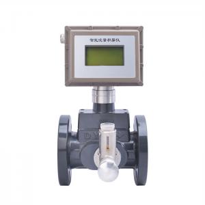
The temperature and pressure compensated gas turbine flowmeter integrates a gas turbine flow sensor and a flow totalizer. Its main performance indicators are up to And the ideal instrument for gas trade measurement.
working principle
When the airflow enters the flow meter, it first passes through the
rectifier with a special structure and is accelerated. Under the
action of the fluid, the turbine overcomes the resistance torque
and friction torque and starts to rotate. When the torque reaches
balance, the rotational speed is stable. The rotational speed of
the turbine is proportional to the gas flow, and the magnetic field
is periodically changed by the magnet on the rotating transmitter
disk, so that the pulse generator outputs a pulse signal with a
frequency proportional to the flow rate. The microprocessor in the
converter counts and calculates the pulse signal to obtain the
working condition flow rate. At the same time, it detects the
temperature and pressure of the medium, converts the working
condition volume flow rate into the standard volume flow rate
according to the volume correction model, and accumulates it to
obtain the standard volume total amount. .
Calculation formula
For example: DN40 caliber gas turbine flowmeter, flow range
5-50m3/h, F-1 is set to 0 (instantaneous quantity displays mh,
cumulative quantity displays m3), F-8 is set to 0.001, F-9 is set
to 250ms, this This means that for every accumulated flow of 0.001
m, an equivalent pulse with a pulse width of 250ms and a duty cycle
of 50% will be output, that is, the upper limit frequency is 1000/
(250*2)=2Hz, and the corresponding upper limit of flow is 0.001 *
2*3600-7.2 m3/h, when the instantaneous flow rate is greater than
7.2 m3/h, the frequency of the output equivalent pulse is still
2Hz, that is, the output is saturated.
Instrument coefficient compensation, that is, multi-point polyline correction of the instrument coefficient K (see P16), a total of 1 can be set to 6, (F, K) (i=1, 2,..., 6)
(1) F, is the original frequency, proportional to the flow rate, unit Hz;
К is the dimensionless relationship between the t coefficient at the E frequency point and the instrument coefficient K (P9 parameter), where K is the actual coefficient at the F frequency point, generally obtained by real flow calibration.
(2) Working principle of multi-point polyline correction. The frequency corresponding to the current flow rate Q is F:
F. >F, (i=12...18), according to the specific parameters built into the table, F is the frequency of the last correction point.
Specification
| Instrument caliber | Conventional flow range (m³/h) | Maximum pressure loss*1(kPa) | |
| 25 | S | 4-40 | 1.5 |
| 40 | S | 6-65 | 1.5 |
| 50 | S1 | 7-70 | 1.2 |
| S2 | 10-100 | 1.4 | |
| 80 | S1 | 13-250 | 1.0 |
| S2 | 20-400 | 2.0 | |
| 100 | S1 | 20-400 | 1.0 |
| S2 | 32-650 | 1.5 | |
| 150 | S1 | 50-1000 | 1.0 |
| S2 | 80-1600 | 2.0 | |
| 200 | S1 | 80-1600 | 0.8 |
| S2 | 130-2500 | 1.5 | |
| 250 | S1 | 130-2500 | 0.8 |
| S2 | 200-4000 | 2.0 | |
| 300 | S | 200-4000 | 1.0 |
| 350 | S | 400-8000 | 1.5 |
| 400 | S | 650-13000 | 2.0 |
| Accuracy level | Level 1.5 (Level 1.0 needs to be customized | ||
illustration
1The upper limit pressure loss is the pressure loss when the flow meter works at the upper limit flow point, the medium is air, and the temperature is normal.
2DN20, DN32, DN65, and DN125 are non-national standard products and need to be customized.
Installation location and requirements
1. It is strictly prohibited to weld the pipe flange online with
the flow meter. The flow meter should be removed before welding.
Before installing the flow meter, the debris, welding slag, and
dust in the pipeline should be cleaned.
2. In order to facilitate maintenance and not affect the normal transportation of fluid, it is recommended to set up a bypass pipeline as shown in the figure above.
3. In order to prevent impurities from entering the flow meter, a filter must be installed.
4. The flow meter should be installed horizontally. It is recommended to install a steel expansion joint (compensator) on the back side of the straight pipe section after the flow meter. The expansion joint must meet the nominal diameter and nominal pressure requirements of the pipeline design. The expansion joint is used to compensate for pipeline stress and facilitate the installation and disassembly of the flow meter.
5. If vertical installation is required, please indicate this when ordering, and the product must be configured accordingly. When installed and used, the air flow direction should be from top to bottom.
6. When the flow meter is installed for outdoor use, it is recommended to add a protective cover to prevent rainwater immersion or hot sun exposure, which will affect the service life of the flow meter.
7. There should be no strong external magnetic field interference or strong mechanical vibration around the flow meter.
8. The flow meter needs to be reliably grounded, but it must not be shared with the ground wire of the strong current system.
Application scenarios
Packing & Delivery
FAQ
1. Q: What information need to be provided to choose the suitable
model?
A: Application field, Nominal pressure ,Medium & medium
temperture , Power supply , Output,
Flow range, Accuracy, Connection and other parameters.
2. Q: Are you a trade company or a manufacturer?
A: We are an ISO approved manufacturer specialized in level and
flow measuring instruments.
OEM & ODM service are available. Welcome to visit us in China.
3. Q: What is your MOQ?
A: To start our cooperation, sample order is acceptable.
4. Q: What is your delivery date for the Intelligent Mini Micro
Turbine Fuel Oil Diesel Flow Meter?
A: The delivery date is about 3-15 working days after receipt of
payment.
5. Q: What is your payment terms?
A: We support T/T, PayPal ,Western Union.
For mass production order, it is 30% deposit in advance and 70%
balance before shipment.
6. Q: Do you have a warranty for the Flow Meter?
A: Yes, we have the warranty of 12 months.