
Add to Cart
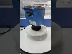
DN15-DN100 Mechanical Indicator Steam Metal Tube Rotameter Variable
Area Sewage Chlorine Oxygen Nitrogen Gas
Description
This product uses a metal tube float or glass rotor flowmeter and a
constant flow valve to form a flow purge device to achieve flow
measurement and ensure constant flow output. Due to the safety and
reliability of the float flowmeter and the characteristics of
accurate and stable measurement, this series of air blowing devices
can ensure constant flow output when the inlet or outlet pressure
changes. It can be widely used in petroleum refining, chemical
industry, ethylene, fertilizer, steel, etc. In the process control
of transmitters in chemical fiber, textile and other industries
such as purging and differential pressure liquid level measurement.
The design structure of this series of products fully meets the
requirements of industrial control, and the applicable installation
conditions fully comply with the requirements of instrument
measurement technology.
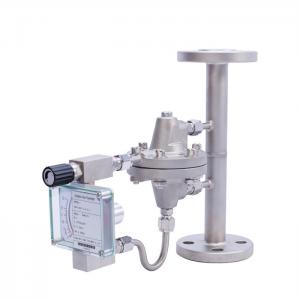
Typical applications under conditions of changing gas supply
pressure are shown on the right: the gas provided by the main
pipeline gas source can be divided into multiple branches as
needed. If the gas flow of several branches is closed or adjusted,
it will cause When the air supply pressure of the main pipeline
changes, the single-channel purging device installed on the support
can accurately measure the flow rate.
Please choose a suitable location to install the flow purge device
to ensure that the flow meter purge device is easy to debug, clean
and disassemble. When installing, make sure the flow direction of
the medium is the same as the direction required by the flow purge
device, and close all the fine-tuning needle valves. Before putting
into operation, please empty and purge the pipeline to avoid
impact. The valve should be opened slowly to adjust to the working
pressure, and the flow rate should be changed by adjusting the
opening of the valve to prevent the float from being impacted,
thereby damaging the measuring components.
specification
| Instrument model | LZB equipped | LZZ equipped with |
| Glass tube float flowmeter | Metal tube float flow meter | |
| Measuring range | ||
| (100% value) | ||
| Water: 20℃ | 3-1001/h | 25-4∞Ol/h |
| Air | 50-3400I/h | 0.7-80m3/h |
| O.1MPa.20℃ | ||
| Range ratio | 10.1 | 10.1 |
| level of accuracy | 4 | 1.5 |
| flow scale | actual flow scale | actual flow scale |
| Medium pressure | Upper limit 1.0MPa | Upper limit 6.4MPa |
| (Special requirements can be added) | ||
| Medium temperature | -20℃ -100℃ | -20℃-200℃ |
| ambient temperature | -20℃-60℃ | -20'C-60℃ |
| Media material | 304 316 | 304 316 |
| shell | Plastic PVC | Cast button, epoxy resin sprayed |
| process connection | ||
| card cover | φ6mmφ8mmφ10mm | φ6πrnφ8mmφ10mm |
| Thread | 1/4W〃 NPT | 1/4W〃NPT |
| 1/2〃NPT | 1/2〃NPT | |
| flange | 1/2〃ANSI 1501b | 1/2〃ANSI 150Ib |
| DIN2501 .HG .GB | DIN2501.HG.GB | |
| special | According to user requirements | According to user requirements |
Installation Precautions
Please choose a suitable location to install the flow purge device
to ensure that the flow meter purge device is easy to debug, clean
and disassemble. Since the purge device float flowmeter is equipped
with a collision transfer system, it is necessary to ensure that
the interference field generated by other working equipment does
not affect the measurement results of the flowmeter. When
installing, ensure that the flow purge device is stable and add
Fixed bracket. The installation dimensions should not exceed the
given dimensions by too much or too little to avoid tensile and
compressive forces acting on the purge device. When the liquid
medium contains ferromagnetic particles, a
Be sure to expose any colliding particles in front of the
instrument. Be sure to ensure that the flow direction of the medium
is the same as the direction required by the flow purge device.
When installing the instrument, close all the fine-tuning needle
valves.
close. Before putting into operation, please empty and purge the
pipeline to avoid impact. The valve should be opened slowly to
adjust to the working pressure. The flow rate should be changed by
adjusting the opening of the valve to prevent the float from being
impacted and thereby damaging the measuring components.
| LZ series purge device | |||||||||
| 1. Instrument model: LZ | |||||||||
| 2. Classification models | |||||||||
| B | Choose a glass tube flowmeter (DK series is generally used for glass rotor flow) | ||||||||
| Z | Choose metal tube flowmeter | ||||||||
| WB | Choose a micro-flow metal tube flowmeter | ||||||||
| 3. Purge mode (if it is single table mode, this code does not need to be selected) | |||||||||
| Single pass purge | |||||||||
| 2 | Dual purge | ||||||||
| 3 | Multi-channel purging (special ones can be customized according to user requirements) | ||||||||
| 4.Installation form | |||||||||
| D | single table | ||||||||
| M | Panel type | ||||||||
| 5. Pressure regulation | |||||||||
| RE | Inlet pressure regulation | ||||||||
| RA | Outlet pressure adjustment | ||||||||
| 6. Process connection | |||||||||
| F | Flange connection | ||||||||
| S | Threaded connection | ||||||||
| K | Card sleeve connection | ||||||||
| 0 | According to user requirements | ||||||||
| 7.Material | |||||||||
| P | 304 | ||||||||
| R | 316 | ||||||||
| N | 316L | ||||||||
| 8.other | |||||||||
| L | With pressure display | ||||||||
| G | With magnetic filter | ||||||||
Features
1. METAL STRUCTURE DESIGN
Sturdy all-metal structure design, suitable for measuring gases and
liquids in various industries. one
2. CASE STRUCTURE DESIGN
Can measure process pressure below 6.4MPa
Flow, pressure (optional) on-site indication
3. CONICAL MEASURING TUBE
Single meter installation, panel installation, cabinet installation
(optional), wider measurement range and better measurement
linearity.
4. CONNECTION METHODS
A variety of process connection methods such as flanges, clamps,
and threads are available to suit most factory application needs.
5. MATERIAL OPTIONAL
Stainless steel, titanium, Hastelloy, PTFE, FEP and other
materials. Single channel, dual channel, multi-channel form
(optional)
6. MAGNETIC COUPLING SYSTEM
Use our company's LZ series float flowmeter
Flow, pressure (optional) on-site indication
Packing & Delivery
FAQ
1. Q: What information need to be provided to choose the suitable
model?
A: Application field, Nominal pressure ,Medium & medium
temperture , Power supply , Output,
Flow range, Accuracy, Connection and other parameters.
2. Q: Are you a trade company or a manufacturer?
A: We are an ISO approved manufacturer specialized in level and
flow measuring instruments.
OEM & ODM service are available. Welcome to visit us in China.
3. Q: What is your MOQ?
A: To start our cooperation, sample order is acceptable.
4. Q: What is your delivery date for the Intelligent Mini Micro
Turbine Fuel Oil Diesel Flow Meter?
A: The delivery date is about 3-15 working days after receipt of
payment.
5. Q: What is your payment terms?
A: We support T/T, PayPal ,Western Union.
For mass production order, it is 30% deposit in advance and 70%
balance before shipment.
6. Q: Do you have a warranty for the Flow Meter?
A: Yes, we have the warranty of 12 months.