
Add to Cart
Variable Area Metal Tube Float Flowmeter Gas Level Small Flow
Pointer DN15-DN100
Description
When the fluid filling the pipe flows through the throttling device
in the pipe, the flow stream will form a local contraction at the
throttling piece of the throttling device, thereby increasing the
flow rate and lowering the static pressure, thus creating pressure
before and after the throttling piece. Drop, that is, pressure
difference. The greater the flow rate of the medium, the greater
the pressure difference generated before and after the throttling
member. Therefore, the fluid flow rate can be measured by measuring
the pressure difference. This measurement method is based on the
law of conservation and the law of flow continuity.
The intelligent throttling device (orifice flowmeter) is a new
generation flowmeter that integrates flow, temperature, and
pressure detection functions and can automatically compensate for
temperature and pressure. It adopts microcomputer technology and
new
micropower consumption technology and has powerful functions. ,
compact structure, simple operation and easy to use.
use
LG/FB type standard annular chamber orifice plate and flange
orifice plate throttling device is a scaleless flow measurement
device. It is used in conjunction with pneumatic or electric
differential pressure transmitters or double bellows differential
pressure transmitters. In metallurgy, chemical, petroleum, and
electric power industrial systems, the pressure difference
generated by liquid, gas, and steam flowing through the orifice
plate with a medium temperature of ≤ 400 ℃ is continuously
measured. The transmitter converts the pressure difference signal
into a proportional output signal, and then There are secondary
instruments or regulators that record, indicate or regulate the
measured flow.
Fundamental
Install throttling parts such as orifice plates or nozzles inside
the pipeline. Since the aperture of the throttling part is smaller
than the inner diameter of the pipe, when the fluid flows through
the throttling part, the flow beam cross section suddenly shrinks
and the flow speed accelerates. The static pressure of the fluid at
the rear end of the throttling member decreases, resulting in a
static pressure difference before and after the throttling member
(see Figure 1). There is a definite numerical relationship between
this static pressure difference and the flow rate of the fluid,
consistent with Q=K . Root sign △ P . Use a differential pressure
transmitter (or differential pressure meter) to measure the
differential pressure before and after the throttling member to
measure the flow rate.
Installation requirements
The installation of the throttling device is related to the
following pipe sections and pipe fittings: resistance piece No. 1
and resistance piece No. 2 on the upstream side of the throttling
piece, resistance piece No. 1 on the right side under the
throttling piece, resistance piece No. 2 upstream of the throttling
piece to The pipe section between the downstream No. 1 resistance
piece and the differential pressure signal pipeline, etc.
Specification
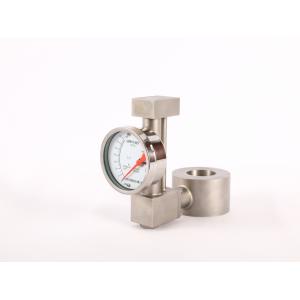
LF-A series integrated orifice flowmeter is a split-flow flowmeter
with floating
The sub-flow meter is installed next to the measuring pipe and is
integrated with the orifice plate for flow splitting.
It has four different connectors for users to choose from, namely
"threaded" (AT),
"Flange" (AF), and "Clamp" (AC), separate type (AD). Fluid flows
through the main
When the orifice plate is installed, a differential pressure is
generated on the front and rear sides of the orifice plate. This
differential pressure value is related to the flow value.
Equivalently, a float flowmeter is installed in the branch inlet
and outlet, so that the flow through the float
The flow rate of the meter is equivalent to the flow rate through
the main pipe, so the fluid passing through the main pipe
The flow rate can be indicated by the scale of the glass float
flowmeter.
·Medium temperature: PVC: 0~60℃,
SS304:0~120℃
·Accuracy: ±2.5%
·Working pressure: 1.0MPa
| DN(mm) | Flow range | ||
| WATER(m3/h) | AIR(Nm3/h) | ||
| 10 | 3/8” | 0.08-0.42 | 0.8-4 |
| 15 | 1/2” | 0.18-0.96 | 2-9.2 |
| 20 | 3/4” | 0.45-2.4 | 5-23 |
| 25 | 1” | 0.8-4.2 | 8-40 |
| 32 | 1-1/4" | 1.2-6.4 | 12-60 |
| 40 | 1-1/2" | 1.8-9.4 | 18-90 |
| 50 | 2” | 3.5-18.5 | 35-175 |
| 65 | 2-1/2" | 6-32 | 60-300 |
| 80 | 3” | 8-42 | 80-400 |
| 100 | 4” | 16-80 | 160-800 |
| 125 | 5” | 25-125 | 250-1250 |
| 150 | 6” | 35-180 | 350-1700 |
| 200 | 8” | 60-320 | 600-2800 |
| 250 | 10” | 90-480 | 900-5000 |
| 300 | 12" | 160-820 | 1600-7800 |
| 350 | 14” | 200-1000 | 2000-9500 |
| 400 | 16” | 300-1500 | 3000-14500 |
| 450 | 18” | 400-2000 | 4000-19000 |
| 500 | 20" | 500-2500 | 5000-24000 |
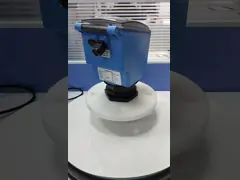
Installation direction:
The installation direction of the LF-A orifice flowmeter can be
changed as shown in the figure on the right. The flow direction is:
bottom → top,
Left→right, right→left and top→bottom, it is very easy to change
the flow direction of the flowmeter in the field.
Packing & Delivery
FAQ
1. Q: What information need to be provided to choose the suitable
model?
A: Application field, Nominal pressure ,Medium & medium
temperture , Power supply , Output,
Flow range, Accuracy, Connection and other parameters.
2. Q: Are you a trade company or a manufacturer?
A: We are an ISO approved manufacturer specialized in level and
flow measuring instruments.
OEM & ODM service are available. Welcome to visit us in China.
3. Q: What is your MOQ?
A: To start our cooperation, sample order is acceptable.
4. Q: What is your delivery date for the Intelligent Mini Micro
Turbine Fuel Oil Diesel Flow Meter?
A: The delivery date is about 3-15 working days after receipt of
payment.
5. Q: What is your payment terms?
A: We support T/T, PayPal ,Western Union.
For mass production order, it is 30% deposit in advance and 70%
balance before shipment.
6. Q: Do you have a warranty for the Flow Meter?
A: Yes, we have the warranty of 12 months.