
Add to Cart
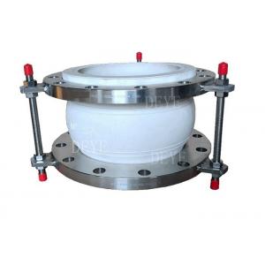
PTFE Joint Expansion Rubber With Food Grade DN50-DN800
Our PTFE expansion joints are made from the synthetic material
Polytetrafluoroethylene, the non reactive material is widely used
in pipelines
within the chemical manufacturing industry, acting as a protective
agent against corrosive substances.
PTFE Polytetrafluoroethylene also has less surface friction than
rubber, which means that flow can be improved by using PTFE hoses.
While rubber is prone to break down at extreme temperatures, PTFE
is highly temperature resistant, making it ideal for all kinds of
industries.
The PTFE liner serves as a primary skin to the fluid being
transferred while the body of the rubber or metal expansion joint
serve as a
secondary measure to prevent leakage from the joint. The PTFE also
gives metal joints added protection against corrosion by keeping
the liquid away from the metal convolutions.
Material of main Spare Parts
| Cover | EPDM, NBR, Hypalon, NR, PTFE |
| Reinforcing Fabric | Nylon |
| Tube | EPDM, NBR, Hypalon, NR, PTFE |
| Retain Rings | Steel |
| Flange | Carbon Steel, Stainless Steel, Duplex SS |
Supplying Scope
| Size Range | DN50-DN800 |
| PN10 PN16 PN25 for rubber |
| PN10, PN16, PN25, PN40, PN64, PN100 for metal bellow type |
Design Pressure
| Working Pressnre(Bar) | 10 | 16 | 25 |
| Burst pressure(Bar) | 30 | 48 | 55 |
| Vacuam(mmHg) | 400 | 650 | 750 |
Technology/ Technical Data Sheets
Spherical Single Sphere Rubber Expansion Joint
Dimension for Rubber joint PN16
| Nominal diameter DN | Length L( mm)
| NO.of bolt n | Flange Holes Dia. | Dia. Of bolt Circle
| Axial displacement (mm) | Lateral displacement
| Angle of deflection
| |||
| (mm) | (in) | Stretch | Compression | |||||||
| 32 | 11/4 | 95 | 4 | 17.5 | 100 | 6 | 9 | 9 | 15° | |
| 40 | 11/2 | 95 | 4 | 17.5 | 110 | 6 | 10 | 9 | 15° | |
| 50 | 2 | 105 | 4 | 17.5 | 125 | 7 | 10 | 10 | 15° | |
| 65 | 21/2 | 115 | 4 | 17.5 | 145 | 7 | 13 | 11 | 15° | |
| 80 | 3 | 135 | 130 | 8 | 17.5 | 160 | 8 | 15 | 12 | 15° |
| 100 | 4 | 150 | 135 | 8 | 17.5 | 180 | 10 | 19 | 13 | 15° |
| 125 | 5 | 165 | 160 | 8 | 17.5 | 210 | 12 | 19 | 14 | 15° |
| 150 | 6 | 180 | 185 | 8 | 22 | 240 | 12 | 20 | 22 | 15° |
| 200 | 8 | 190 | 200 | 8 | 22 | 295 | 16 | 25 | 22 | 15° |
| 250 | 10 | 230 | 240 | 12 | 22 | 350 | 16 | 25 | 22 | 15° |
| 300 | 12 | 245 | 260 | 12 | 22 | 400 | 16 | 25 | 22 | 15° |
| 350 | 14 | 265 | 16 | 26 | 460 | 16 | 25 | 22 | 15° | |
| 400 | 16 | 265 | 16 | 26 | 515 | 16 | 25 | 22 | 15° | |
| 450 | 18 | 265 | 20 | 26 | 565 | 16 | 25 | 22 | 15° | |
| 500 | 20 | 265 | 20 | 30 | 620 | 16 | 25 | 22 | 15° | |
| 600 | 24 | 265 | 20 | 26 | 725 | 16 | 25 | 22 | 15° | |
| 700 | 28 | 260 | 24 | 30 | 810 | 16 | 25 | 22 | 10° | |
| 800 | 32 | 260 | 24 | 30 | 920 | 16 | 25 | 22 | 10u | |
| 900 | 36 | 260 | 24 | 30 | 1020 | 16 | 25 | 22 | 10w | |
| 1000 | 40 | 260 | 28 | 30 | 1120 | 16 | 25 | 22 | 10° | |
Dimension of Rubber joint 150LBS
| Nominal diameter DN | Length L(mm) | b | NO.of bolt | Dia. Of Flange holes | Dia. Of Bolt Circle. PCD | Axial displacement | Lateral displacement | Angle of deflection | |||
mm | |||||||||||
| (mm)(in) | L1 | L2 | stretch | Compression | |||||||
| 25 | 1 | 152 | 130 | 14 | 4 | 16 | 79.4 | +9.5 | 13 | ±13 | ±15° |
| 32 | 1 1/4 | 152 | 130 | 16 | 4 | 16 | 89 | +9.5 | 13 | ±13 | ±15° |
| 40 | 1-1/2 | 152 | 130 | 16 | 4 | 16 | 98.5 | +9.5 | -13 | ±13 | ±15" |
| 50 | 2 | 152 | 130 | 16 | 4 | 19 | 121 | +9.5 | 13 | ±13 | ±15" |
| 65 | 2-1/2 | 152 | 130 | 18 | 4 | 19 | 139.5 | +9.5 | -13 | ±13 | ±15 |
| 80 | 3 | 152 | 130 | 18 | 4 | 19 | 153 | +9.5 | -13 | ±13 | ±15° |
| 100 | 4 | 152 | 130 | 18 | 8 | 19 | 190 | +9.5 | 16 | ±13 | ±15° |
| 125 | 5 | 152 | 130 | 20 22 | 8 | 22.5 | 216 | +9.5 | -16 | ±13 | ±15° |
| 150 | 6 | 152 | 130 | 8 | 22.5 | 242 | +9.5 | -16 | ±13 | ±15° | |
| 200 | 8 | 152 | 130 | 22 | 8 | 22.5 | 298 | +9.5 | -16 | ±13 | ±15° |
| 250 | 10 | 203 | 130 | 24 | 12 | 25.5 | 362 | +13 | 16 | ±19 | ±15° |
| 300 | 12 | 203 | 130 | 24 | 12 | 25.5 | 432 | +13 | 19 | ±19 | ±15° |
| 350 | 14 | 203 | 200 | 26 | 12 | 28.5 | 476 | +13 | -19 | ±19 | ±15° |
| 400 | 16 | 203 | 200 | 28 | 16 | 28.5 | 540 | +13 | -19 | ±19 | ±15° |
| 450 | 18 | 203 | 200 | 30 | 16 | 32 | 578 | +13 | -19 | ±19 | ±15° |
| 500 | 20 | 203 | 200 | 30 | 20 | 32 | 634 | +13 | -19 | ±19 | ±15° |
| 600 | 24 | 254 | 260 | 32 | 20 | 35 | 749.5 | +13 | -19 | ±19 | ±15° |
| 800 | 32 | 254 | 260 | 36 | 24 | 30 | 920 | +13 | -19 | ±19 | ±15° |
FEATURES
Absorb Axial movements (extension and compression).
Axial movement is the change in dimensional length of the bellows
from its free length in a
direction parallel to its longitudinal axis.
Absorb Lateral movements.
Lateral movement is the relative displacement of one end of the
bellows to the other end in a direction perpendicular to its
longitudinal axis.
Absorb Angular and Torsional Movements.
Angular movement is the rotational displacement of the longitudinal
axis of the bellows toward a point of rotation. Torsion refers to
twisting one
end of the bellows with respect to the other end, about the bellows
centerline.
Reduce Vibration.
Rubber expansion joints isolate or reduce vibration caused by
equipment. The transmission
of vibration is reduced and they protect equipment from these
adverse effects
Dampen Sound Transmission.
Rubber expansion joints tend to dampen transmission of sound
because of the steel rubber interface of joints and mating flanges.
Manual and Install Notes of the Rubber Joint
Application:
Oil & gas, Desalination, Cooling systems, Pumps, Chemical
plants, Heating, ventilating
and air conditioning, Shipbuilding, Off-shore applications, Water
treatment plants
Sewage, Sanitary piping systems, Pulp and paper plants, Piping
systems for chilled or hot water, Cooling systems power generation,
Phosphate plants, Potable water, Food process


