
Add to Cart
Description
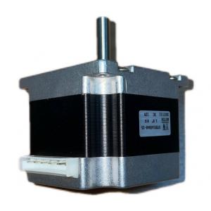
DC motor voltage 36V factory Customised Hot sales electric motor
power 60W used for Intelligent furniture
The rotor stacks have number of teeth equals to stator teeth number
but they are aligned.
Essential details
Voltage(V): | 36V | Torque(Nm): | 2Nm |
Input power(W): | 60W | Current(A): | 2A |
Detailed Information
As a matter of fact, not all stepper motors have the same internal
structure (or construction), as there are different rotor and
stator configurations.
Rotor For a stepper motor, there are basically three types of
rotors: Permanent magnet rotor: The rotor is a permanent magnet
that aligns with the magnetic field generated by the stator
circuit. This solution guarantees a good torque and also a detent
torque. This means the motor will resist, even if not very
strongly, to a change of position regardless of whether a coil is
energized.
The drawbacks of this solution is that it has a lower speed and a
lower resolution compared to the other types. The rotor is made of
an iron core, and has a specific shape that allows it to align with
the magnetic field (see Figure 1 and Figure 2). With this solution
it is easier to reach a higher speed and resolution, but the torque
it develops is often lower and it has no detent torque. Hybrid
rotor: This kind of rotor has a specific construction, and is a
hybrid between permanent magnet and variable reluctance versions.
The rotor has two caps with alternating teeth, and is magnetized
axially.
This configuration allows the motor to have the advantages of both
the permanent magnet and variable reluctance versions, specifically
high resolution, speed, and torque.
This higher performance requires a more complex construction, and
therefore a higher cost. Figure 3 shows a simplified example of the
structure of this motor. When coil A is energized, a tooth of the
N-magnetized cap aligns with the S-magnetized tooth of the stator.
At the same time, due to the rotor structure, the S-magnetized
tooth aligns with the N-magnetized tooth of the stator. Real motors
have a more complex structure, with a higher number of teeth than
the one shown in the picture, though the working principle of the
stepper motor is the same. The high number of teeth allows the
motor to achieve a small step size, down to 0.9°.
Hybrid Stepper Motor Stator The stator is the part of the motor
responsible for creating the magnetic field with which the rotor is
going to align.
The main characteristics of the stator circuit include its number
of phases and pole pairs, as well as the wire configuration. The
number of phases is the number of independent coils, while the
number of pole pairs indicates how main pairs of teeth are occupied
by each phase. Two-phase stepper motors are the most commonly used,
while three-phase and five-phase motors are less common (see Figure
5 and Figure 6). Figure 5: Two-Phase Stator Winding (Left),
Three-Phase Stator Winding (Right) wo-Phase, Single-Pole Pair
Stator (Left) and Two-Phase, Dipole Pair Stator (Right). The
Letters Show the Magnetic Field Generated when Positive Voltage is
Applied between A+ and A-.