
Add to Cart
Essential details
AC Voltage:240V
Place of Origin:Guangdong, China
Brand Name:GO-GOLD
Model Number:KG-8016-1
Type:Induction Motor
Frequency:50/60Hz
Phase:Single-phase
Protect Feature:Drip-proof
Efficiency:IE 2, 30-40%
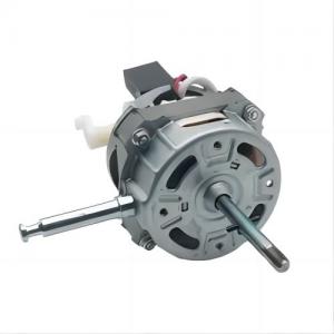
Product Name:Fan motor
Rated Power:50W
Usage:Fan,kitchen,appliances,floor fan
Speed:1200RPM
Voltage:240V
Keywords:Fan motor
Brand:GO-GOLD
Motor type:KG-8016-1
Material:Copper, iron, aluminum, plastic
Warranty:3years
Packaging & delivery
Port:Shenzhen
Lead time:
| Quantity(pieces) | 1 - 1000 | 1001 - 10000 | >10000 |
| Lead time (days) | 15 | 30 | To be negotiated |
Performance specification
| Voltage: | 240V | Frequency: | 50/60Hz |
| Input power: | 50W | Rated speed: | 1200RPM |
Induction motor structure
The stator of an induction motor consists of three parts: the
stator core, stator winding, and frame. The stator core is a part
of the main magnetic circuit. In order to reduce the eddy currents
and hysteresis losses generated by the excitation current and
rotating magnetic field in the iron core, the iron core is stacked
with 0.5mm thick silicon steel sheets. For motors with larger
capacity, both sides of the silicon steel sheet are coated with
insulation paint as interlayer insulation. The small stator core is
stacked and compressed into a whole with silicon steel sheets, and
then fixed in the frame; Medium and large stator cores are
assembled by fan-shaped punching pieces. There are many slots with
the same shape uniformly punched in the inner circle of the stator
core to embed the stator winding. Small induction motors typically
use a semi closed slot and a single layer (loose down) winding made
of high-strength enameled wire, with slot insulation between the
coil and the iron core. A semi closed slot can reduce the magnetic
resistance of the main magnetic circuit and reduce the excitation
current, but embedding wires is less convenient. Medium induction
motors typically use half open slots. Large high-voltage induction
motors all use open slots for easy wire insertion. In order to
achieve good electromagnetic performance, both medium and large
induction motors use double-layer short pitch windings.
The rotor is composed of a rotor core, rotor winding, and shaft.
The rotor core is also a part of the main magnetic circuit, usually
composed of 0.5mm thick silicon steel sheets stacked together, and
the core is fixed on the shaft or rotor bracket. The outer surface
of the entire rotor is cylindrical. The rotor winding is divided
into two types: cage type and winding type.
Cage rotor
A cage winding is a self closing winding composed of guide bars
inserted into each rotor slot and ring end rings at both ends. If
the iron core is removed, the entire winding is shaped like a
"circular cage", hence it is called a cage winding. To save copper
and improve productivity, small cage motors generally use cast
aluminum rotors; For medium and large motors, due to the difficulty
in ensuring the quality of cast aluminum, a structure of inserting
copper bars into the rotor slot and welding end rings at both ends
is adopted. The cage type induction motor has a simple structure
and convenient manufacturing, making it an economical and durable
motor. So it has a wide range of applications.
Wound rotor
A three-phase winding composed of insulated wires embedded in the
slot of a wound rotor, with the three outgoing terminals of the
winding connected.
It is connected to three Slip ring on the rotating shaft, and then
led out through the brush. This rotor is characterized by that
external resistance can be connected in the rotor winding to
improve the starting and speed regulating performance of the motor.
Compared with cage rotor, wound rotor has a slightly complex
structure and is slightly more expensive, so it is only used in
situations where low starting current, high starting torque, or
dispatch is required.