
Add to Cart
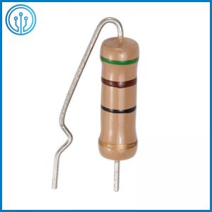
Cylindrical Fixed Carbon Film Resistor 1~10M Ohm 1/8W 1/6W 0.25W
0.5W 1W 2W 3W
Overview Of The Cylindrical Fixed Carbon Film Resistor
Carbon film resistors are a type of film resistors. It uses
high-temperature vacuum coating technology to closely attach carbon
to the surface of the porcelain rod to form a carbon film, then add
appropriate joints for cutting, and coat the surface with epoxy
resin for sealing protection. The surface is often painted with
green protective paint. The thickness of the carbon film determines
the size of the resistance, and the thickness of the film and the
notch are usually used to control the resistor. Carbon film
resistors are also called "thermal decomposition carbon film
resistors". A type of thin film resistor in which carbon is
deposited on the substrate by carbon that is thermally decomposed
at high temperature in a vacuum. Low price, stable performance,
wide resistance value and power range.
Application Of The Cylindrical Fixed Carbon Film Resistor
The typical uses for carbon film resistors are in high voltage and
high temperature applications. Operating voltages can be as high as
15 kV with nominal temperatures of 350°C. Example uses include high
voltage power supplies, radars, x-rays, and lasers.
Features Of The Cylindrical Fixed Carbon Film Resistor
• Flameproof coating is available (specify “CFR”)
• Reduced body size (specify “Miniature”)
• Suitable for automatic machine insertion
• Products with lead-free terminations meet EU RoHS and China RoHS
requirements
• Available in resistances from 1 Ohm to 9.1 mOhm
• 1/8W ~ 5W power rating
• 5% tolerance
• Resistor body 2.3 mm in diameter, 6.3 mm in length
• Carbon film construction
• Long-term stability
• Solder plated copper leads
Electrical Parameters Of The Cylindrical Fixed Carbon Film Resistor
Type | Rated power | Maximum working | Maximum overload | Dielectric withstanding | Resistance | |
| Normal size | CF1/8W | 0.125W | 200V | 400V | 350V | 1Ω~10MΩ |
| CF1/4W | 0.25W | 250V | 500V | 500V | 1Ω~10MΩ | |
| CF1/2W | 0.5W | 350V | 700V | 700V | 1Ω~10MΩ | |
| CF1W | 1W | 500V | 800V | 800V | 1Ω~10MΩ | |
| CF2W | 2W | 500V | 1000V | 1000V | 1Ω~10MΩ | |
| CF3W | 3W | 500V | 1000V | 1000V | 1Ω~10MΩ | |
| CF5W | 5W | 500V | 1000V | 1000V | 1Ω~10MΩ | |
| Small size | CF1/4WS | 0.25W | 250V | 400V | 350V | 1Ω~10MΩ |
| CF1/2WS | 0.5W | 350V | 700V | 500V | 1Ω~10MΩ | |
| CF1WS | 1W | 500V | 800V | 700V | 1Ω~10MΩ | |
| CF2WS | 2W | 500V | 1000V | 800V | 1Ω~10MΩ | |
| CF3WS | 3W | 500V | 1000V | 1000V | 1Ω~10MΩ | |
| CF5WS | 5W | 500V | 1000V | 1000V | 1Ω~10MΩ | |
Dimension Of The Cylindrical Fixed Carbon Film Resistor (mm)
| Type | Dimensions | |||||
Normal Size | Small Size | I | L | ψD | ψd | H |
| CF1/8W | CF1/4WS | 60 | 3.2±0.5 | 1.8±0.5 | 0.43±0.05 | 28.0±2.0 |
| CF1/4W | CF1/2WS | 60 | 6.5±0.5 | 2.3±0.5 | 0.45±0.05 | 28.0±2.0 |
| CF1/2W | CF1WS | 60 | 9.0±0.5 | 3.2±0.5 | 0.50±0.05 | 28.0±2.0 |
| CF1W | CF2WS | 60 | 11.5±1.0 | 4.5±0.5 | 0.7 0±0.05 | 25.0±2.0 |
| 81 | 11.5±1.0 | 4.5±0.5 | 0.7 0±0.05 | 35.0±2.0 | ||
| 94 | 11.5±1.0 | 4.5±0.5 | 0.7 0±0.05 | 42.0±2.0 | ||
| CF2W | CF3WS | 60 | 15.0±1.0 | 5.0±0.5 | 0.70±0.05 | 23.0±2.0 |
| 70 | 15.0±1.0 | 5.0±0.5 | 0.70±0.05 | 28.0±2.0 | ||
| 81 | 15.0±1.0 | 5.0±0.5 | 0.70±0.05 | 33.0±2.0 | ||
| 94 | 15.0±1.0 | 5.0±0.5 | 0.70±0.05 | 40.0±2.0 | ||
| CF3W | CF5WS | 94 | 17.5±1.0 | 6.0±0.5 | 0.70±0.05 | 38.0±2.0 |
| CF5W | 94 | 24.5±1.0 | 8.0±0.5 | 0.70±0.05 | 35.0±2.0 | |
NO | Item | Material |
| 1 | Ceramic core | High alumina ceramic is used. |
| 2 | Resistor element | The resistor element shall consist of carbon film. |
| 3 | Terminal | Tinned iron cap. |
| 4 | Connection | The lead wire, which is plated with solder, shall be mounted to the caps by welding process. |
| 5 | Lead wire | Soldered or tinned annealed wire. |
| 6 | Undercoat painting | Electric insulation resin. |
| 7 | Finishing painting | Epoxy resin is used. |
| 8 | Indication | Color code. |
M Type Formed Of The Cylindrical Fixed Carbon Film Resistor
Watts | Dimensions (mm) | |||
| ΦD | L | P±1.0 | H±1.0 | |
| 1/8w,1/6w | 1.8±0.3 | 3.2±0.5 | 6 | 8 |
| 1/4w,1/2ws | 2.3±0.5 | 6.5±0.5 | 10 | 8 |
| 1/2w,1ws | 3.5±0.5 | 9.5±0.5 | 12.5/15 | 10 |
| 1w,2ws | 4.5±1.0 | 11.5±1.0 | 15 | 10 |
| 2w,3ws | 5.0±1.0 | 15.5±1.0 | 20 | 10 |
| 3w | 6.0±1.0 | 17.5±1.0 | 25 | 10 |
| 5w | 8.0±1.0 | 24.5±1.0 | 30 | 10 |
What do the colours mean?
Each of the colour bands has a specific meaning. The first two
colours give the base value of the resistor, the next gives the
multiplier and the final band the tolerance. If a resistor has five
bands, it is a more precise resistor, in which the first three
bands represent the base values, and the fourth and fifth represent
the multiplier and tolerance respectively.
Benefits of Carbon Composition
Carbon composition resistors are made from a moulded carbon powder
that has been mixed with a phenolic resin to bind and create a
uniform resistive body. It is then surrounded in an insulating case
after attaching end leads.
Carbon composition resistors are used in applications in which the
initial tolerance does not need to be any closer than +/- 5% of the
value.