
Add to Cart
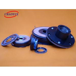
DLD7 Single Disc ELECTORMAGNETIC CLUTCH 12 - 60 Mm
Noteedit
1) Since the electromagnetic clutch is engaged and disengaged at a
high speed, there will be many clutch marks on the surface of the
iron absorption plate and the rotor. These traces will not cause
harm to the work and are allowed.
2) Appropriate voltage should be applied to the electromagnetic
coil. For a 12V voltage electromagnetic coil, if it is added to a
6V voltage system, it will not be able to generate enough magnetic
field, which will cause the suction iron to slip, shorten the life
of the clutch, and reduce the cooling capacity. Conversely, if a 6V
coil is added to a 12V voltage system, the coil life will be
shortened.
3) The gap between the coil and the rotor is very important. The
coil and the rotor should be as close as possible to obtain a
stronger magnetic field, but the gap should not be too small to
prevent the rotor from dragging the coil (for fixed-coil clutches).
4) The gap between the rotor and the iron absorption is also very
important. If this gap is too small, when the clutch is disengaged,
the rotor will drag the suction iron. But if the gap is too large,
there will be too little contact between them when the clutch is
working. Both of these conditions can cause poor clutch
performance. The reasonable gap between the two should be that when
the clutch has no current, the two will not drag; when the clutch
has current, it can ensure that no slipping occurs.
Mounting example
| Model | DLD7 - 5 | DLD7 - 10 | DLD7 - 20 | DLD7 - 40 | DLD7 - 80 | DLD7 - 160 | DLD7 - 320 | ||||||||
| Friction Torque[N.m] | Dynamic | 5 | 10 | 20 | 40 | 80 | 160 | 320 | |||||||
| Static | 5.5 | 11 | 22 | 45 | 90 | 175 | 350 | ||||||||
| Excitation Voltage [V] | DC - 24V | ||||||||||||||
| Power (20°C) [w] | 15 | 20 | 28 | 35 | 50 | 68 | 85 | ||||||||
| Max Rotating Speed [rpm] | 8000 | 6000 | 5000 | 4000 | 3000 | 3000 | 2000 | ||||||||
| Weight [kg] | 0.79 | 1.2 | 2.24 | 3.86 | 7 | 13.3 | 21.2 | ||||||||
Radial Size [mm] | D1 | 63 | 80 | 100 | 125 | 160 | 200 | 250 | |||||||
| D2 | 46 | 60 | 76 | 95 | 120 | 158 | 210 | ||||||||
| D3 | 34.5 | 41.7 | 51.5 | 61.5 | 79.5 | 99.5 | 124.5 | ||||||||
| B | 68 | 85.5 | 107 | 134.3 | 170 | 214 | 266.5 | ||||||||
| C | 57 | 68 | 85 | 100 | 127 | 152.4 | 152.4 | ||||||||
| G1 | 38 | 47 | 56 | 64.5 | 86.5 | 100 | 127 | ||||||||
| G2 | 46.5 | 55 | 64 | 72.5 | 101.5 | 115 | 142 | ||||||||
| V1 | 3 - 4.1 | 3 - 4.2 | 3 - 5.2 | 3 - 6.2 | 3 - 8.2 | 3 - 10.2 | 3 - 12.2 | ||||||||
| V2 | 3 - 6.3 | 3 - 9.5 | 3 - 11.5 | 3 - 13.5 | 3 - 17.5 | 3 - 21.5 | 3 - 26.5 | ||||||||
| V3 | 3 - 6.25 | 3 - 8.3 | 3 - 10.3 | 3 - 12.35 | 3 - 16.35 | 3 - 20.42 | 3 - 25 | ||||||||
| Y1 | 4.1 | 8.1 | |||||||||||||
| Y2 | 14 | 18 | 22 | 26 | |||||||||||
Axial Size [mm] | H | 26.1 | 28.1 | 32.5 | 36.3 | 41.6 | 47.7 | 55.2 | |||||||
| L1 | 44.3 | 44.7 | 55 | 61.5 | 70.7 | 85 | 93.5 | ||||||||
| L2 | 39.8 | 43.2 | 49 | 54.5 | 61.5 | 73.5 | 81 | ||||||||
| P | 7.7 | 8.2 | 9.2 | 9.8 | 15.2 | 16.5 | 19.5 | ||||||||
| R | 3 | 4 | |||||||||||||
| X | 2.5 | 2.85 | 3.3 | 3.5 | 4.9 | 5.5 | |||||||||
| δ | 0.2 ± 0.05 | 0.3 ( +0.05 / -0.1) | 0.5 (0 / -0.2) | ||||||||||||
Bore Size [mm] | D | 12 | 15 | 20 | 25 | 30 | 40 | 50 | 60 | ||||||
| b | 4 | 5 | 6 | 8 | 12 | 14 | 18 | ||||||||
| t | 13.8 | 17.3 | 22.8 | 28.3 | 33.3 | 43.3 | 53.8 | 64.4 | |||||||

