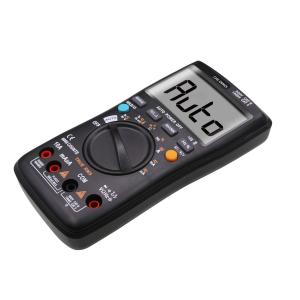
0.001V 0.01V 0.1V Digital EMF Meter With Small Voltage Range
Brand Name:CHX
Certification:CE, RoHS
Model Number:CHX-DM025
Minimum Order Quantity:10pc
Delivery Time:5-35days
Payment Terms:T/T, Western Union,Paypal,L/C
Contact Now
Add to Cart
Active Member
Location:
Shenzhen Guangdong China
Address:
502, No. 31, Yangmei Road, Bantian Street, Shenzhen, Guangdong, China
Supplier`s last login times:
within 47 hours
Product Details
Company Profile
Product Details
0.001V / 0.01V / 0.1V Electromagetic Field Tester ± (0.8% of reading + 5 words)
Description
1.2.1 When using, you must use the correct function and range.
1.2.2 Do not exceed the protection range of each range to measure
the value.
1.2.3 Do not touch the top of the test leads (metal parts) when the
meter is connected to the measuring circuit.
1.2.4 In the measurement, if the measured voltage is higher than
60V DC or 30V AC (RMS), should pay attention to keep the fingers
always in the table after the finger care device.
1.2.5 Do not measure the voltage when the voltage between the
measuring end and the earth exceeds AC 600V.
1.2.6 Before turning the change switch to change the measuring
function, remove the test leads from the circuit under test.
1.2.7 Do not live measurement resistance, capacitance, diode and
test circuit off.
1.2.8 In the current, resistance, capacitance, diode and line
continuity test range, care should be taken to avoid connecting the
meter to the voltage source.
1.2.9 Do not measure the capacitance until the capacitor is fully
discharged.
1.2.10 Do not use this instrument near explosive gas, steam or
dust.
1.2.11 If you notice any abnormality or malfunction of the
instrument, stop using it.
1.2.12 Do not use the instrument unless the instrument case and
battery cover are fully fastened in place.
1.2.13 Do not store or use the instrument in direct sunlight, high
temperature, high humidity.
Maintenance
1.4.1 Do not attempt to open the bottom case to adjust or repair
the instrument. This operation can only be performed by a
technician who is fully aware of the instrument and the risk of
electric shock.
1.4.2 Before opening the instrument case or battery cover, remove
the test leads from the circuit under test.
1.4.3 In order to avoid false alarms that may cause errors, when
the meter displays the "" symbol,Replace the battery immediately.
1.4.4 Use a damp cloth and mild detergent to clean the meter, do
not use abrasives or solvents.
1.4.5 When the instrument is not in use, turn off the power and
turn the range switch to the OFF position.
1.4.6 If the instrument is not used for a long time, remove the
battery to prevent damage to the instrument.
Technical indicators
Ambient temperature: 23 ± 5 ℃ Relative humidity: <75%
3.2.1 True rms zero input
3.2.1.1 The measurement of sine wave signal, the use of true RMS
measurement method than the traditional average response method
error is small.
3.2.1.2 True RMS The instrument can accurately measure the sine
wave signal, but if it is on the AC function, the instrument may
display 1 to 50 if the measured signal is not input (shorted at the
AC voltage range and the input terminal) Word between a reading.
These deviations are normal. Within the specified measuring range,
they do not affect the accuracy of the multimeter to measure
alternating current.
3.2.1.3 True RMS requires that the input signal reach a certain
level for measurement. Therefore, the AC voltage and current range
is specified between 2% and 100% of full scale.
3.2.2 DC voltage
| Range | Resolution | Accuracy |
| 6V | 0.001V | ±(0.5% of reading + 5 words) |
| 60V | 0.01V | |
| 600V | 0.1V | ±(0.8% of reading + 5 words) |
- Input impedance: 10MΩ
- Maximum input voltage: 600V DC or 600V AC (rms)
Note:
In the small voltage range, the pen is not connected to the circuit
under test, the instrument may have beating the reading,
This is normal, this is because the instrument caused by high
sensitivity, does not affect the actual measurement results.
3.2.3 AC voltage
| Range | Resolution | Accuracy |
| 6V | 0.001V | ±(0.8% of reading + 3words) |
| 60V | 0.01V | |
| 600V | 0.1V | ±(1.0% of reading + 10words) |
- Input impedance: 10MΩ
- Maximum input voltage: 600V AC (RMS) or 600V DC
- Frequency range: 40 ~ 1000Hz True RMS
Note:
In the small voltage range, the pen is not connected to the circuit
under test, the instrument may have beating the reading,
This is normal, this is because the instrument caused by high
sensitivity, does not affect the actual measurement results.
3.2.4 Alternating current
| Range | Resolution | Accuracy |
| 600.0uA | 0.1uA | ±(1.5% of reading +10words) |
| 6000uA | 1uA | |
| 60.00mA | 0.01mA | |
| 600.0mA | 0.1mA | |
| 6A | 0.001A | ±(2.5% of reading +10words) |
| 10A | 0.01A |
- Overload protection: mA range fuse (self-recovery fuse 200mA /
250V)
10A range without insurance
- Maximum input current: mA: 600mA DC or AC rms;
10A: 10A DC or AC rms;
When the measured current is greater than 5A, the continuous
measurement time is not longer than 15 seconds, after the
measurement to stop the current measurement for more than 1 minute.
- Frequency response: 40Hz ~ 1000Hz True RMS.
3.2.5 DC
| Range | Resolution | Accuracy |
| 600.0uA | 0.1uA | ±(1.0% of reading +5words) |
| 6000uA | 1uA | |
| 60.00mA | 0.01mA | |
| 600.0mA | 0.1mA | |
| 6A | 0.001A | ±(2.0% of reading +10words) |
| 10A | 0.01A |
- Overload protection: mA range fuse (self-recovery fuse 200mA /
250V)
10A range without insurance
- Maximum input current: mA: 600mA DC or AC rms;
10A: 10A DC or AC rms;
When the measured current is greater than 5A, the continuous
measurement time is not longer than 15 seconds, after the
measurement to stop the current measurement for more than 1 minute.
3.2.6 Frequency
| Range | Resolution | Accuracy |
| 9.999Hz | 0.001Hz | ±(1.0% of reading +3words) |
| 99.99Hz | 0.01Hz | |
| 999.9Hz | 0.1Hz | |
| 9.999kHz | 0.001kHz | |
| 99.99KHZ | 0.01kHZ | |
| 999.9KHZ | 0.1KHZ | |
| 9.999MHZ | 0.001MHZ |
- Overload protection: 250V DC or AC (rms)
- Input voltage range: 600mV ~ 10V AC (with the measured frequency
increases, the input voltage should also increase)
3.2.7 Duty cycle
| Range | Resolution | Accuracy |
| 0.1 – 99.9% | 0.1% | ± 3.0% |
- Frequency response: 10 ~ 10MHz
- Input voltage range: 600mV ~ 10VAC (with the measured frequency increases, the input voltage should also increase)
- Maximum input voltage: 250V AC (rms)
Resistance
| Range | Resolution | Accuracy |
| 600W | 0.1W | ±(0.8% of reading +3words) |
| 6kW | 0.001kW | |
| 60kW | 0.01kW | |
| 600kW | 0.1kW | |
| 6MW | 0.001MW | ±(1.2% of reading +3words) |
| 60MW | 0.01MW |
- Open circuit voltage: approx. 1.0V
- Overload protection: 250V DC or AC (rms)
Transistor test
| Range | Description | Test Conditions |
| hFE | The display reads the approximate value of hFE(0~1000) | Base current of about 10uA; Vce about 2.8V |
Capacitance
| Range | Resolution | Accuracy |
| 9.999nF | 0.001nF | ±(4.0% of reading +3words) |
| 99.99nF | 0.01nF | |
| 999.9nF | 0.1nF | |
| 9.999mF | 0.001mF | |
| 99.99mF | 0.01mF | |
| 999.9mF | 0.1mF | |
| 9.999mF | 0.001mF | ±(5.0% of reading +3words) |
| 99.99mF | 0.01mF | Not calibrated |
- Overload protection: 250V DC or AC (rms)
Temperature test
| Range | Accuracy | Resolution |
| -20℃-300℃ | ±(1.0%+4d) | 1℃ |
| 301℃-1000℃ | ±(1.9%+5d) | 1℃ |
| -4℉-600℉ | ±(1.2%+6d) | 1℉ |
| 601℉-1832℉ | ±(1.9%+6d) | 1℉ |
- Overload protection: 250V DC or AC (rms)


0.001V 0.01V 0.1V Digital EMF Meter With Small Voltage Range
Inquiry Cart
0