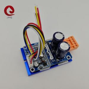
3 Phase Brushless Dc Motor Driver Board V8.5E With Heatsink And Connector Wires
Brand Name:JUYI
Certification:CE,
Model Number:JYQD-V8.5E
Minimum Order Quantity:1 set
Delivery Time:5-10 days
Payment Terms:T/T,L/C,Paypal
Contact Now
Add to Cart
Verified Supplier
Location:
Changzhou Jiangsu China
Address:
No.299 Changjiang North Rd, Changzhou City, JIangsu, China
Supplier`s last login times:
within 3 hours
Product Details
Company Profile
Product Details
3 Phase No-Hall Brushless Dc Motor Driver Board V8.5E, No- Inductive Motor Controller With Heatsink And Connector Wires
(For Brushless Sensorless DC motor )
Application notes:
| 1. Confirm that the voltage and power parameters of the motor not exceed the range of the driver board as specified. |
2. This driver board is used for 3-phase brushless sensorless
motor, but not suit for all 3-phase brushless sensorless motors
directly. If the driving effect is not good (such as starting
jitter, reversing, the motor noload working current is too large,
the speed is not stable, the efficiency is low, and can’t start-up
with load.) Customers can adjust the resistance and capacitance of
the driver board according to the actual situation to achieve the
best driving effect (see the attachment for how to do the
adjustment) |
3. JYQD-V8.3E driver board is bare board without housing and
heatsink. If the power of the motor below 60W ,it does not need to
add heatsink, It only needs to ensure normal ventilation and well
insulation. If the power of the motor more than 60W, it must add
heatsink like the diagram as below. |
4. Please take note that JYQD-V8.3E driver board has no
anti-reverse connection protection,
it will permanently damage the driver board if reversed polarity connection.
5. The 5V output port on the driver board prohibits connect
external device. It is only applicable
to the external potentiometer and switch of the board for speed
regulation and reversal.
6. The “M” terminal on the JYQD-V8.3E driver board is the motor
speed pulse output signal (push-pull output),
and the maximum output current is less than 5mA.
| Model number | JYQD-V8.5E |
| Operating temp. | -20—85℃ |
| Operating voltage | 18V-50V |
| Max current | 15A |
| Cont.working current | 15A |
| · PWM speed control | PWM frequency:1-20KHZ; Duty cycle 0-100% |
| Analog voltage speed regulation | 0-5V |
| O.V / L.V protection | YES |
| Speed pulse signal output | YES |
Wiring diagram
| 5V | Driver board internal output voltage |
| M | Motor speed pulse signal output port, 5V pulse signal. |
| Z/F | Rotating direction control ports. Connect “5V” high level or no connect is Forward direction, connect 0 V low level or connect to GND is reverse direction. |
| VR | Speed control port. Analog voltage linear speed regulation 0.1v -5V, The input resistance is 20K Ohm ,connect with GND when input PWM speed regulation, PWM frequency:1-20KHZ; Duty cycle 0-100% |
| GND | Used for Drive board internal control |
2. Power port
| MA | motor phase A |
| MB | motor phase B |
| MC | motor phase C |
| GND | DC- |
| VCC | DC + |
3. Use shielded wires if the drivers board has more than 50 cm
distance from the motor, otherwise
it may lead to abnormal driving, affecting the normal use.
4.Control port distance: 2.54mm,Power port distance:3.96 mm
5. Pay attention to the insulation between the driver MOSFET and
the heatsink or the installation plate.
Dimensional drawing:
add connector wires , heatsink.


3 Phase Brushless Dc Motor Driver Board V8.5E With Heatsink And Connector Wires
Inquiry Cart
0