
Add to Cart
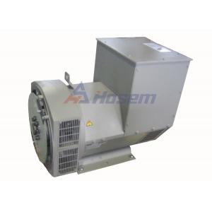
STANDARDS OF 100KVA BRUSHLESS ALTERNATOR
1. Stamford industrial generators meet the requirements of BS EN
60034 and the relevant section of other international standards
such as BS5000, VDE 0530, NEMA MG1-32, IEC34, CSA C22.2-100,
AS1359.
2. Other standards and certifications can be considered on request.
VOLTAGE REGULATORS SX460 AVR - STANDARD
1. With this self excited control system the main stator supplies
power via the Automatic Voltage Regulator (AVR) to the exciter
stator. The high efficiency semiconductors of the AVR ensure
positive build-up from initial low levels of residual voltage.
2. The exciter rotor output is fed to the main rotor through a
three phase full wave bridge rectifier. This rectifier is protected
by a surge suppressor against surges caused, for example, by short
circuit.
AS440 AVR FOR BRUSHLESS ALTERNATOR
1. With this self-excited system the main stator provides power via
the AVR to the exciter stator. The high efficiency semi- conductors
of the AVR ensure positive build-up from initial low levels of
residual voltage.
2. The exciter rotor output is fed to the main rotor through a
three- phase full-wave bridge rectifier. The rectifier is protected
by a surge suppressor against surges caused, for example, by short
circuit or out-of-phase paralleling.
3. The AS440 will support a range of electronic accessories,
including a 'droop' Current Transformer (CT) to permit parallel
operation with other ac generators.
MX341 AVR FOR BRUSHLESS ALTERNATOR
1. This sophisticated AVR is incorporated into the Stamford
Permanent Magnet Generator (PMG) control system.
2. The PMG provides power via the AVR to the main exciter, giving a
source of constant excitation power independent of generator
output. The main exciter output is then fed to the main rotor,
through a full wave bridge, protected by a surge suppressor. The
AVR has in-built protection against sustained over-excitation,
caused by internal or external faults. This de- excites the machine
after a minimum of 5 seconds.
3. An engine relief load acceptance feature can enable full load to
be applied to the generator in a single step.
4. If three-phase sensing is required with the PMG system the MX321
AVR must be used.
5. We recommend three-phase sensing for applications with greatly
unbalanced or highly non-linear loads.
MX321 AVR
1. The most sophisticated of all our AVRs combines all the features
of the MX341 with, additionally, three-phase rms sensing, for
improved regulation and performance.
2. Over voltage protection is built-in and short circuit current
level adjustments is an optional facility.
WINDINGS & ELECTRICAL PERFORMANCE
All generator stators are wound to 2/3 pitch. This eliminates
triplen (3rd, 9th, 15th …) harmonics on the voltage waveform and is
found to be the optimum design for trouble-free supply of
non-linear loads. The 2/3 pitch design avoids excessive neutral
currents sometimes seen with higher winding pitches, when in
parallel with the mains. A fully connected damper winding reduces
oscillations during paralleling. This winding, with the 2/3 pitch
and carefully selected pole and tooth designs, ensures very low
waveform distortion.
TERMINALS & TERMINAL BOX
Standard generators are 3-phase reconnectable with 12 ends brought
out to the terminals, which are mounted on a cover at the non-drive
end of the generator. A sheet steel terminal box contains the AVR
and provides ample space for the customers' wiring and gland
arrangements. It has removable panels for easy access.
SHAFT & KEYS
All generator rotors are dynamically balanced to better than
BS6861:Part 1 Grade 2.5 for minimum vibration in operation. Two
bearing generators are balanced with a half key.
INSULATION/IMPREGNATION
1. The insulation system is class 'H'.
2. All wound components are impregnated with materials and
processes designed specifically to provide the high build required
for static windings and the high mechanical strength required for
rotating components.
QUALITY ASSURANCE
1. Generators are manufactured using production procedures having a
quality assurance level to BS EN ISO 9001.
2. The stated voltage regulation may not be maintained in the
presence of certain radio transmitted signals. Any change in
performance will fall within the limits of Criteria 'B' of EN
61000-6-2:2001. At no time will the steady-state voltage regulation
exceed 2%.
DE RATES
1. All values tabulated on page 8 are subject to the following
reductions
2. 5% when air inlet filters are fitted.
3. 3% for every 500 metres by which the operating altitude exceeds
1000 metres above mean sea level.
4. 3% for every 5°C by which the operational ambient temperature
exceeds 40°C.
5. Requirement for operating in an ambient exceeding 60°C must be
referred to the factory.
| 100KVA BRUSHLESS ALTERNATOR WITH WINDING 311 | ||||||||
| CONTROL SYSTEM | SEPARATELY EXCITED BY P.M.G. | |||||||
| A.V.R. | MX321 | MX341 | ||||||
| VOLTAGE REGULATION | ± 0.5 % | ± 1.0 % | With 4% ENGINE GOVERNING | |||||
| SUSTAINED SHORT CIRCUIT | REFER TO SHORT CIRCUIT DECREMENT CURVES (page 7) | |||||||
| CONTROL SYSTEM | SELF EXCITED | |||||||
| A.V.R. | SX460 | AS440 | ||||||
| VOLTAGE REGULATION | ± 1.0 % | ± 1.0 % | With 4% ENGINE GOVERNING | |||||
| SUSTAINED SHORT CIRCUIT | SERIES 4 CONTROL DOES NOT SUSTAIN A SHORT CIRCUIT CURRENT | |||||||
| INSULATION SYSTEM | CLASS H | |||||||
| PROTECTION | IP23 | |||||||
| RATED POWER FACTOR | 0.8 | |||||||
| STATOR WINDING | DOUBLE LAYER CONCENTRIC | |||||||
| WINDING PITCH | TWO THIRDS | |||||||
| WINDING LEADS | 12 | |||||||
| STATOR WDG. RESISTANCE | 0.059 Ohms PER PHASE AT 22°C SERIES STAR CONNECTED | |||||||
| ROTOR WDG. RESISTANCE | 1.12 Ohms at 22°C | |||||||
| EXCITER STATOR RESISTANCE | 20 Ohms at 22°C | |||||||
| EXCITER ROTOR RESISTANCE | 0.091 Ohms PER PHASE AT 22°C | |||||||
| R.F.I. SUPPRESSION | BS EN 61000-6-2 & BS EN 61000-6-4,VDE 0875G, VDE 0875N. refer to factory for others | |||||||
| WAVEFORM DISTORTION | NO LOAD < 1.5% NON-DISTORTING BALANCED LINEAR LOAD < 5.0% | |||||||
| MAXIMUM OVERSPEED | 2250 Rev/Min | |||||||
| BEARING DRIVE END | BALL. 6315-2RS (ISO) | |||||||
| BEARING NON-DRIVE END | BALL. 6310-2RS (ISO) | |||||||
| 1 BEARING | 2 BEARING | |||||||
| WEIGHT COMP. GENERATOR | 406 kg | 420 kg | ||||||
| WEIGHT WOUND STATOR | 131 kg | 131 kg | ||||||
| WEIGHT WOUND ROTOR | 133.78 kg | 122.82 kg | ||||||
| WR² INERTIA | 1.0288 kgm2 | 0.9781 kgm2 | ||||||
| SHIPPING WEIGHTS in a crate | 439 kg | 452 kg | ||||||
| PACKING CRATE SIZE | 105 x 67 x 103(cm) | 105 x 67 x 103(cm) | ||||||
| 50 Hz | 60 Hz | |||||||
| TELEPHONE INTERFERENCE | THF<2% | TIF<50 | ||||||
| COOLING AIR | 0.514 m³/sec 1090 cfm | 0.617 m³/sec 1308 cfm | ||||||
| VOLTAGE SERIES STAR | 380/220 | 400/231 | 415/240 | 440/254 | 416/240 | 440/254 | 460/266 | 480/277 |
| VOLTAGE PARALLEL STAR | 190/110 | 200/115 | 208/120 | 220/127 | 208/120 | 220/127 | 230/133 | 240/138 |
| VOLTAGE SERIES DELTA | 220/110 | 230/115 | 240/120 | 254/127 | 240/120 | 254/127 | 266/133 | 277/138 |
| kVA BASE RATING FOR REACTANCE VALUES | 100 | 100 | 100 | N/A | 112.5 | 117.5 | 117.5 | 125 |
| Xd DIR. AXIS SYNCHRONOUS | 2.45 | 2.21 | 2.05 | - | 2.76 | 2.58 | 2.36 | 2.3 |
| X'd DIR. AXIS TRANSIENT | 0.2 | 0.18 | 0.17 | - | 0.24 | 0.22 | 0.21 | 0.2 |
| X''d DIR. AXIS SUBTRANSIENT | 0.14 | 0.13 | 0.12 | - | 0.16 | 0.15 | 0.14 | 0.13 |
| Xq QUAD. AXIS REACTANCE | 1.59 | 1.43 | 1.33 | - | 1.58 | 1.48 | 1.35 | 1.32 |
| X''q QUAD. AXIS SUBTRANSIENT | 0.18 | 0.16 | 0.15 | - | 0.23 | 0.21 | 0.2 | 0.19 |
| XL LEAKAGE REACTANCE | 0.07 | 0.06 | 0.06 | - | 0.08 | 0.07 | 0.07 | 0.07 |
| X2 NEGATIVE SEQUENCE | 0.16 | 0.14 | 0.13 | - | 0.19 | 0.18 | 0.16 | 0.16 |
| X0 ZERO SEQUENCE | 0.1 | 0.09 | 0.08 | - | 0.12 | 0.11 | 0.1 | 0.1 |
| REACTANCES ARE SATURATED | VALUES ARE PER UNIT AT RATING AND VOLTAGE INDICATED | |||||||
| T'd TRANSIENT TIME CONST. | 0.028 s | |||||||
| T''d SUB-TRANSTIME CONST. | 0.001 s | |||||||
| T'do O.C. FIELD TIME CONST. | 0.8 s | |||||||
| Ta ARMATURE TIME CONST. | 0.007 s | |||||||
| SHORT CIRCUIT RATIO | 1/Xd | |||||||
| ASF 274 C A.C. Brushless Alternator Ratings 50Hz 0.8 Power Factor Winding 311 | ||||||||||||||||
| Class - Temp Rise | Cont. F - 105/40°C | Cont. H - 125/40°C | Standby - 150/40°C | Standby - 163/27°C | ||||||||||||
| Series Star (V) | 380 | 400 | 415 | 440 | 380 | 400 | 415 | 440 | 380 | 400 | 415 | 440 | 380 | 400 | 415 | 440 |
| Parallel Star (V) | 190 | 200 | 208 | 220 | 190 | 200 | 208 | 220 | 190 | 200 | 208 | 220 | 190 | 200 | 208 | 220 |
| Series Delta (V) | 220 | 230 | 240 | 254 | 220 | 230 | 240 | 254 | 220 | 230 | 240 | 254 | 220 | 230 | 240 | 254 |
| kVA | 84 | 84 | 84 | N/A | 100 | 100 | 100 | N/A | 106 | 106 | 106 | N/A | 110 | 110 | 110 | N/A |
| kW | 67.2 | 67.2 | 67.2 | N/A | 80 | 80 | 80 | N/A | 84.8 | 84.8 | 84.8 | N/A | 88 | 88 | 88 | N/A |
| Efficiency (%) | 90.7 | 91.1 | 91.3 | N/A | 89.8 | 90.3 | 90.6 | N/A | 89.5 | 90 | 90.4 | N/A | 89.2 | 89.8 | 90.2 | N/A |
| kW Input | 74.1 | 73.8 | 73.6 | N/A | 89.1 | 88.6 | 88.3 | N/A | 94.7 | 94.2 | 93.8 | N/A | 98.7 | 98 | 97.6 | N/A |