
Add to Cart
The horizontal pneumatic type winding / reeling machine with good
performance
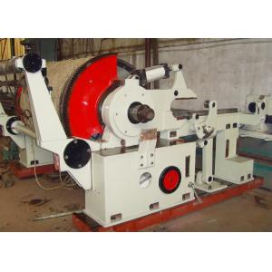
The Horizontal pneumatic type winding / reeling machine is matched
with a paper machine with the same net paper width, and is used to
roll the paper into a tight and uniform roll.
During operation, the paper roll roller abuts on the rotating paper
roll cylinder and is driven to rotate by surface friction. The line
pressure between the paper roll and the paper roll cylinder can be
adjusted by controlling the intake air pressure of the cylinder and
the main arm cylinder through the console. Therefore, it can meet
the needs of different paper types, so that the paper can be rolled
into a tight and uniform roll.
Because the paper roll roller is purely driven by the friction of
the surface of the paper roll cylinder, as the diameter of the
paper gradually increases, the speed of the paper roll is
correspondingly reduced, and no additional speed adjustment is
required, which is convenient to operate.
This series of products are divided into left and right arrangement
according to the transmission position. Standing at the end of the
paper roll to face the machine. The device located on the left side
is called the left mobile phone (represented by the letter Z), and
the user should pay attention to the same direction as the paper
machine used
Main specification of the referred machine :
| Model | 1880 |
| Frame type | Pneumatic |
| Control way | Electric ,air control |
| Paper winding linear pressure | 2-4N/mm |
| Spreading roll | movable curve roll |
| Max winding roll diameter | Φ1600mm |
| Working speed | 250m/min |
| Winding cylinder | Φ1100×2180 |
| Winding roll size | Φ240×223 |
| C-C distance | 3000 |
| Over all size | 3300×4380×1950 |
This series of products are made of the corresponding paper roll
cylinder, paper roll, stretching device, scraper, connecting shaft
and main arm, jib transmission, frame, pneumatic operation box,
paper roll brake, paper shelf, electrical equipment etc.
1. Roll paper cylinder device:
The device is composed of a gas-water rotary joint, a transmission
side bearing, an operation side bearing, and a paper roll cylinder.
2. Paper roll device
The device is composed of a fixed-end bearing, a floating-end
bearing, a half coupling, a paper roll and the like.
The paper roll consists of a bulkhead, a shaft head, a roller body
and a bearing, a semi-coupling, etc. After assembly, it is fully
calibrated and balanced to meet the needs of high-speed rotation on
the paper rewinding frame of the rewinder.
3. Stretching device
The device consists of a movable arc-shaped roller and a supporting
frame foot. Its role is to make the web fully stretched before
entering the roll cylinder to avoid folding and wrinkling during
winding.
4.Scraper device
In order to keep the surface of the paper roll cylinder constantly
clean, a scraper device is provided. It is fixed on a bracket
inside the rack. A handle connected to the blade head of the
scraper body is provided on the outside of the operating side
frame, and the scraper can be lifted by pulling it, so as to
regularly clean up the dirt on the blade edge.
5. Jib device
The jib device is composed of a jib, a fan gear, an air cylinder
and a pressure rod. The whole device is sleeved on the two bearing
seats of the paper roll cylinder, and can be driven by the jib
transmission device to rotate around this bearing. Its main
function is to catch a new paper roll at a starting position tilted
20 ° forward and move it to a level of about 45 ° from the
horizontal (for cardboard, this angle is about 60 °). Roll
position, after the unwinding is completed and the paper web is
normally rolled up, move it to the horizontal rail of the rack as
soon as possible.
In this process, for the sake of safety, the paper roll roller is
always pressed against the paper roll cylinder to generate the
necessary pressure of the paper roll line, so that the paper roll
does not jump when the paper is rotated, the paper web does not
wrinkle, and the paper roll is tight Even and moderate tightness,
two auxiliary cylinders are equipped. Especially when the paper
roll is moved to the horizontal guide without being caught by the
main arm, the roll paper line pressure due to the component force
generated by the paper roll's own weight has dropped to zero. At
this time, the required line pressure is completely It is realized
by the auxiliary cylinder until all the main arms are connected to
the main body. That is to say, at this time, the auxiliary cylinder
can be depressurized, and the pressure lever can be retracted. When
the diameter of the paper roll increases, the paper roll roller
bearings are all moved away from the shorter side of the jib fork
about 15mm, the jib can be raised to the starting position to
accept the task of the next cycle.
The pressure of the roll paper line varies depending on the paper
type, which can be achieved by adjusting the intake air pressure of
the cylinder through the operating table.
6.Boom device
The main arm device is composed of a main arm, a turning mechanism
and a cylinder. The main arm can be rotated around the support
fixed to the bottom rail (commonly known as the base plate) by the
cylinder pushing or pulling. Its main function is to hold the paper
roll on the jib and continuously apply pressure to it, so that a
certain linear pressure is generated between the paper roll and the
roll cylinder, so as to ensure the tightness of the paper roll.
This line of pressure can be realized by adjusting the inlet
pressure through the operating table according to the needs of the
paper type. After reaching the predetermined maximum roll paper
diameter, push the roll back. Then return to the starting position
to "execute" the next cycle of work.
The main arm is provided with a turning mechanism, which guarantees
that under any circumstances, that is, whether the jib first moves
the paper roll to the horizontal guide, and then the main arm comes
over to catch it, or the main arm waits for the Start position, and
then the jib moves the paper roll to the horizontal guide rail,
which can achieve the purpose of catching smoothly
7. Jib transmission
The jib transmission is composed of a motor, a worm gear reducer, a
safety clutch, a pinion, and a connecting shaft. The rotation of
the jib is realized by this system. According to the technological
requirements and structural arrangements, the jib catches the new
paper roll at the starting position inclined 20 ° forward, and the
roll surface of the paper roll is in contact with the cylinder
surface of the paper roll when it is rotated backward about 32 °.
By the friction of the cylinder surface, the linear velocity is
equal to the linear velocity of the paper roll cylinder, and the
paper is drawn up. After the full width of the paper web is drawn
in and normal, you can lower it evenly and move it on the
horizontal guide rail of the rack. As mentioned above, when the
paper roll roller bearings are all moved about 15mm away from the
shorter side of the fork of the jib, the motor can be reversed to
return the jib to its starting position with no load.
In order to prevent the paper roll from moving forward due to
inertia after the power of the motor is cut off, that is, the
action is delayed, a brake is arranged at the high speed shaft so
that once the power is cut off, the entire transmission system is
stopped. Considering that when the jib with the rolled paper roll
(paper roll) is lowered to the horizontal rail at a uniform speed,
once the stroke switch fails, the motor continues to run in the
same direction, the gearbox will be damaged due to excessive load,
and the motor will be damaged. Or break the fork of the jib, so a
safety clutch is also set, that is, it automatically slips when the
load is too large, which plays a protective role
8.Rack device
The device is composed of front and rear supports, horizontal guide
rails, bottom rails, etc., and supports most parts. To ensure
safety, protective railings are provided.
9.Paper roll brake
The paper roll brake is used to stop the rotating paper roll before
lifting. So that the journal of the paper roll is not severely worn
due to being suspended due to rotation. The brake is fixed on the
outside of the rear support of the machine frame (for wide and high
speed), and a space is provided on the inside for pneumatic
braking, which is conducive to the operation of the lifting hook.
It uses the friction torque between the friction plate riveted on
the brake plate and the half couplings fixed at both ends of the
paper roll to brake the entire paper roll.
Pneumatically operated equipment

