
Add to Cart
Wired Wireless Mouse Chip USB Interface Integrated IC Optical Mouse
Chip
Chip name: Optical mouse chip
Mouse chip model: GZ-P001-1622
Pin function:
The pinout functions of the chip are as follows:
D+, D-: Differential data lines of the USB interface. When the USB
interface is not used, D+ is pulled high and D- is connected low.
PS2CLK/Ser, PS2Data (Muse Warrior 20 O, Mousse Warrior 20 V, Mousse
Warrior 24 Wheel): PS/2 mouse interface line, connected to the host
interface. PS2CLK can be used as the output of the serial port,
connected to the RS232 driver chip to drive the serial mouse TXD
line. When not in use, it must be suspended (internally pulled up).
PS2CLK, PS2Data (MouseWarrior24 EyeII): PS/2 mouse interface line,
connected to the host interface. When not in use, it must be
suspended (internally pulled up).
RTS (MuseWarrior20 O, MouseWarrior20V, MouseWarrior24Wheel): Serial
RTS signal input requires external auxiliary circuit. When the pin
is pulled low, the serial port data transmission is stopped, and
the chip is reset when it changes from low to high. This pin must
be pulled low when the serial port is not used.
ADB: ADB interface data line, must be left floating when not in use
(internal pull-up).
North, Sooth, East, West (MouseWarrior 20 V): Connect with the
Intellink Electronics VersaPointTM sensor. When the maximum
external force acts on the sensor, a resistor should be connected
to this pin for use in the dual integration circuit to discharge
the capacitor (see the example introduction for details).
X1, X2, Y1, Y2 (MouseWarrior20 O, MouseWarrior24 Wheel): Optical
integral coding or the signal input of the mouse mechanical part,
X1 falling edge before X2 falling edge means right shift, Y1
falling edge before Y2 falling edge. The photoelectric converter
must have a pull-down resistor or use a Schmitt trigger
photodetector.
PD, SDIO, SCLK (MouseWarrior24 EyeII): These pins can be directly
connected to the corresponding pins of the ADNS2051 sensor
(internal pull-up).
Z1/Down, Z2/Up (MuseWarrior24 Wheel, MouseWarrior24 EyeII): Optical
integral code input by sliding the scroll wheel or buttons. This
function can be activated through the Buttons pin. The falling edge
of Z1 precedes the falling edge of Z2, which means sliding upward.
It is pulled up internally by a resistor, and the photoelectric
converter or button must be pulled down to ground.
Buttons (Muse Warrior 24 Wheel, Mousse Warrior 24 Eye II): When
using the scroll wheel function, this pin is floating. When using
the button to generate the sliding function, this pin is grounded,
and the sliding button is connected to the Z1/Down, Z2/Up pins
(internal pull-up).
En (MuseWarrior20 O, MouseWarrior24Wheel): The LED enable signal of
the optical integral encoder. Open-drain output, which can absorb
24mA current, requires an external resistor.
En (MouseWarrior24 EyeII): The power enable signal of HDNS2000
(optical sensor chip). Open-drain output, internally pulled up by a
resistor, requires an external auxiliary circuit.
Left, Right, Center: Left, right and middle mouse button input. For
internal pull-up, the input signal must be close to ground.
4th (MuseWarrior20 V, MouseWarrior24Wheel, MouseWarrior24 EyeII):
Input the 4th mouse button. For internal pull-up, the input signal
must be close to ground.
5th (MouseWarrior24 EyeII): Input the 5th mouse button. For
internal pull-up, the input signal must be close to ground.
CExt: When USB is suspended to check the wake-up condition, this
pin is used to wake up the processor periodically. An external RC
circuit is required.
Pull to GND: This pin is used to ground the MouseWarrior final
product.
XOut, XIn: External 6MHz ceramic oscillator (quartz oscillator may
cause instability), no other auxiliary devices are needed. An
external 6MHz clock signal can also be input to the XIn pin, and
the XOut pin should be left floating.
GD: power ground.
Vcc: The positive pole of the power supply.
figure 2
Working characteristics and interface description:
The MouseWarrior chip performs a series of reset operations when it
is powered on. When the power is just turned on, all internal
pull-ups are disabled, and they are enabled during the reset
operation. After the initialization is completed, MousseWarrior
detects which mouse interface is active. If no active interface is
detected within 5s, MousseWarrior uses the PS/2 interface mode by
default.
When using USB universal serial interface mode, MouseWarrior is
used as a standard human-machine interface device (HID), compatible
with standard drivers, and the country code is 0. MouseWarrior 20 O
defines 3 mouse keys, Mouse Warrior 20V defines 4 mouse keys, Mouse
Warrior 24 Wheel and Mouse Warrior 24 Eye II defines 4 mouse keys
and scroll wheel.
When using the PS/2 interface mode, the MouseWarrior device is
marked as 0, which defines the left, center, and right keys to be
compatible with the standard drive of the system. MouseWarrior 24
Wheel and Mouse Warrior 24 EyeII are compatible with the PS/2
interface equipment of the Microsoft Internet Explorer TM protocol.
Their device number can be defined as 3-with a scroll wheel device
attached, or as 4-with a fourth button attached.
As ADC (Apple Computer Desktop Bus Apple Desktop Bus) and serial
mouse are currently less used in China, they will not be repeated
here. Those who are interested can refer to the relevant
literature.
Application circuit:
Figure 2 shows the mouse circuit designed with MouseWarrior 20 V,
and the sensor interface circuit is marked in the figure. The
circuit supports USB, ADC, PS/2 and serial interfaces. Readers can
choose according to their needs, and end users can also choose the
appropriate interface.
Working voltage | 4.5V~5.5V |
Interface type | USB PS2 |
Lens ratio | 1:1 |
DPI | 800/1200 (default) |
Current (mobile) | 20mA |
Current (not moving) | 5mA |
Current (power down) | 0.5Ma |
Package | DIP12 |
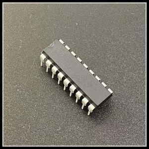
Product image presentation: