Laboratory Spring Hammer Impact Testing Machine Calibration Device OEM
Brand Name:GSKA
Certification:CE SGS ROHS UL CE
Model Number:Universal Tensile Testing Machine
Minimum Order Quantity:Negotiate
Delivery Time:10-60days after confirmed payment or by contract stipulation
Payment Terms:L/C, T/T
Contact Now
Add to Cart
Active Member
Location:
Dongguan Guangdong China
Address:
Room 401, Building 3, No. 10, Longxi Road, Nancheng Street, Dongguan, Guangdong
Supplier`s last login times:
within 30 hours
Product Details
Company Profile
Product Details
Laboratory Spring Hammer Impact Testing Machine Calibration Device
Product information:
The Calibration device for spring hammer is designed and
manufactured according to the standard requirements of
IEC60068-2-75 and GB2423.55, it is used for the calibration of the
spring hammer testers between 0 and 2 J.
Because it is difficult to measure directly for the offered energy
of the calibrated spring hammer, the calibration principle of this
device is by comparing the energy which is calculated by the mass
of the pendulum and drop height.
The highest resolution capability of this device is 0.01J. The
release mechanism is improved in the design, it can maximum reduce
vibration affect on the test when the the spring hammer lease, the
pendulum rod and aerospace bearing are made of imported good
quality steel, so that to improve the precision and stability of
the device.
Technical parameters:
| Accuracy | 0.01J |
| The maximum measuring range | 0-2J |
| Impact energy | Max. 2J |
| Guide groove diameter | 51mm |
| The energy loss of the pendulum | <0.002J |
| Trigger distance | >30mm |
Notice and maintenance:
1.The pendulum rod can not have any swing before the spring hammer
tester is triggered.
2.Stop swinging the release wheel after the spring hammer tester is
triggered
3.Operating environment: 25 ±5℃ , temperature 60-80%, prevent
vibration.Procedure for the calibration of spring hammers:
Principle of calibration:
The principle of this calibration procedure is to compare the
energy provided by a spring hammer, which is difficult to measure
directly, to the energy of a pendulum, calculated from its mass and
height of fall.
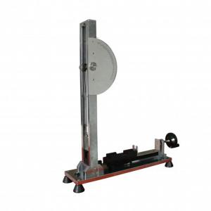
Construction of the calibration device:
The assembled calibration device is shown in figure B.1. Apart from
the frame, the main parts are a bearing “a”, a drag pointer “b ”, a
pendulum “c”, a release base “d” and a release device “e”.
The main part of the calibration device is the pendulum “c” shown
in figure B.2. To the lower end of this pendulum is fixed a steel
spring with the details shown in figure B.3. The spring is of
spring steel, requiring no special treatment, and is rigidly fixed
to the pendulum “c”.
Figure B.4 shows some parts on a large scale
It should be noted that this spring is designed for calibrating
spring hammers having characteristics as defined in table 1 for
energy values equal to or less than 1 J. For calibrating spring
hammers having characteristics as defined for 2 J, the spring of
the pendulum of the calibrating device would need to be of a
different design.
In order to obtain suitable friction characteristics of the
pointer, a piece of thick woven cloth is placed between the metal
surfaces of the bearing, the piano wires being bent in such a way
that a small force is exerted against the cloth.
Because the release device is removed during the calibration of the
calibration device, the release device is fixed to the release base
by means of screws.
Method of calibration of the calibration device:
The calibration of the calibration device is effected by using a
calibration striking element “g” taken from a spring-hammer, as
shown in figure B.5. Before calibration, the release device is
removed from the calibration device.
The calibration striking element is suspended by four linen threads
“h” from suspension points situated in a horizontal plane, 2000 mm
above the point of contact between the pendulum and the calibration
striking element when the latter is in its rest position. The
calibration striking element is allowed to swing against the
pendulum and the point of contact under dynamic conditions, point
“k”, shall be not more than 1 mm below the point of contact in the
rest position. The suspension points are then raised over a
distance equal to the difference between both contact points.
When the suspension system is adjusted, the axis of the calibration
striking element “g” shall be at right angles to the impact surface
of the pendulum “c” and the calibration striking element shall be
horizontal at the moment of impact.
When the calibration striking element is in its rest position, the
calibration device is placed so that point “k” is positioned
exactly at the head of the calibration striking element.
To obtain reliable results, the calibration device is rigidly fixed
to a massive support, for example to a structural part of a
building.
The height of fall is measured at the centre of gravity of the
calibration striking element and the measurement can be facilitated
by using a liquid level device consisting of two glass tubes “j”
which are interconnected by means of a flexible hose. One of the
glass tubes is fixed and provided with a scale “I”.
The calibration striking element may be held in its upper position
by means of a thin thread “m” which, when ruptured, causes the
release of the calibration striking element.
For scaling the calibration device, a circle is drawn on the scale
plate, the centre of this circle coinciding with the bearing of the
pendulum and its radius being such that the circle extends to the
drag pointer. On this circle, the zero point 0 J shown in figure
B.6 is marked at the point indicated by the drag pointer when the
latter is brought into contact with the pendulum in the rest
position.
The calibration is made with an impact energy of 1 J, which is
achieved with a height of fall of 408 mm ± 1 mm, with a calibration
striking element of 250 g.
The point on the scale plate corresponding to 1 J is obtained by
allowing the suspended calibration striking element to swing
against the point “k” on the spring of the pendulum. After hitting
the pendulum, the calibration striking element shall not move. The
operation is repeated at least 10 times and the 1 J point is the
average of the indications of the drag pointer.
The other pints of the scale are then determined as follows:
a) A straight line is drawn through the centre of the circle and
the 0 J point;
b) The orthogonal projection of the 1 J point on this line is
indicated by P;
c) The distance between the points 0 J and P is divided into 10
equal parts;
d) Through each dividing point, a line is drawn perpendicular to
the line 0 J-P;
e) The intersections between these lines and the circle correspond
to values of impact energy equal to 0.1 J; 0.2 J; up to 0.9 J.
The same principle can be used for extending the scale beyond the 1
J point. The division of the scale plate “f” is shown in figure
B.6.
Use of the calibration device:
The spring hammer to be calibrated is put in the release base and
is then operated three times by means of the release device; it
shall not be released manually.
For each operation, the striking element of the spring hammer to be
calibrated is turned in a different position. The average value of
the three readings on the calibration device is taken to be the
actual value of the impact energy of the specimen.
Customer Support Services:
Ø Installation
Ø Training (Training customer employees)
Ø Calibration
Ø Preventative maintenance
Ø Replacement parts
Ø Assistance via phone or internet
Ø On-site diagnosis and repair/online diagnosis and repair


Laboratory Spring Hammer Impact Testing Machine Calibration Device OEM
Inquiry Cart
0