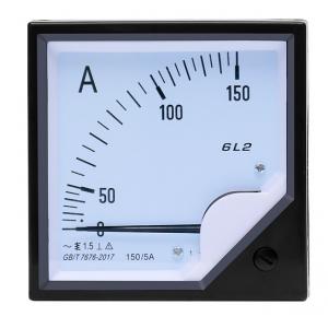
Abs 45-65hz Ac Volt Meter High Precision 5A 99T Three Phase
Brand Name:MC
Certification:CCC,CE
Model Number:6L2
Minimum Order Quantity:10
Delivery Time:3-5 work days
Payment Terms:L/C, D/A, D/P, T/T, Western Union, MoneyGram
Contact Now
Add to Cart
Verified Supplier
Location:
Wenzhou Zhejiang China
Address:
58 Longhe Road, Liushi Town,Wenzhou, Zhejiang, China 325604
Supplier`s last login times:
within 14 hours
Product Details
Company Profile
Product Details
MC 612 multi-function digital display ammeter pointer single-phase ac 4216 digital high precision measurement of 99 t
Introduction
Ammeter refers to a meter used to measure current in AC and DC
circuits. In the circuit diagram, the symbol of the ammeter is
"circle A". The current value takes "A" or "A" as the standard
unit.
The ammeter is made according to the force of the magnetic field on
the energized conductor in the magnetic field. There is a permanent
magnet inside the ammeter, which generates a magnetic field between
the poles. There is a coil in the magnetic field. There is a
hairspring spring at each end of the coil. The springs are
connected to a terminal of the ammeter. The spring and the coil are
connected by a shaft, and the shaft is opposite. At the front end
of the ammeter, there is a pointer. When there is current passing,
the current passes through the magnetic field along the spring and
the rotating shaft, and the current cuts the magnetic induction
line. Therefore, under the action of the magnetic field force, the
coil deflects and drives the rotating shaft and pointer to deflect.
Since the magnitude of the magnetic field force increases with the
increase of the current, the magnitude of the current can be
observed by the degree of deflection of the pointer. This is called
a magnetoelectric ammeter, which is what we usually use in the
laboratory. In the junior high school period, the range of the
ammeter used is generally 0~0.6A and 0~3A
Specification
| Accurate level | 0.5 |
| The instrument type | Programmable instruments, digital display type. |
| Input voltage range | AC 0-100V 0-660V |
| Voltage circuit, power consumption | <2VA |
| Current input range | AC1A 5A |
| The power consumption of the current loop | <1VA |
| Frequency range | 45-65Hz |
| The temperature | -10-45℃ |
The principle
The ammeter is made according to the force of the magnetic field on
the energized conductor in the magnetic field. There is a permanent
magnet inside the ammeter, which generates a magnetic field between
the poles. There is a coil in the magnetic field. There is a
hairspring spring at each end of the coil. The springs are
connected to a terminal of the ammeter. The spring and the coil are
connected by a shaft, and the shaft is opposite. At the front end
of the ammeter, there is a pointer. The pointer is deflected. Since
the magnitude of the magnetic field force increases with the
increase of the current, the magnitude of the current can be
observed by the degree of deflection of the pointer. This is called
a magnetoelectric ammeter, which is what we usually use in the
laboratory.
Generally, currents of the order of microamps or milliamps can be
directly measured. To measure larger currents, the ammeter should
have parallel resistors (also called shunts). Mainly use the
measuring mechanism of the magnetoelectric meter. When the
resistance value of the shunt makes the full-scale current pass,
the ammeter is fully deflected, that is, the ammeter indication
reaches the maximum. For a few amperes of current, a dedicated
shunt can be set in the ammeter. For currents above a few amperes,
an external shunt is used. The resistance value of the high-current
shunt is very small. In order to avoid errors caused by the
addition of lead resistance and contact resistance to the shunt,
the shunt should be made into a four-terminal form, that is, there
are two current terminals and two voltage terminals. For example,
when using an external shunt and millivoltmeter to measure a large
current of 200A, if the standardized range of the millivoltmeter
used is 45mV (or 75mV), then the resistance value of the shunt is
0.045/200=0.000225Ω (or 0.075/200=0.000375Ω). If a ring (or step)
shunt is used, a multi-range ammeter can be made.
Precautions
⒈ Correct wiring.
When measuring current, the ammeter should be connected in series
with the circuit under test; when measuring voltage, the voltmeter
should be connected in parallel with the circuit under test. When
measuring DC current and voltage, you must pay attention to the
polarity of the meter, and make the polarity of the meter
consistent with the polarity being measured.
⒉ Measurement of high voltage and high current.
When measuring high voltage or large current, a voltage transformer
or current transformer must be used. The range of the voltmeter and
ammeter should be consistent with the secondary rated value of the
transformer. Generally, the voltage is 100V and the current is 5A.
⒊ The expansion of measuring range.
When the measurement in the circuit exceeds the range of the meter,
an external shunt or voltage divider can be used, but it should be
noted that its accuracy level should be consistent with the
accuracy level of the meter.
⒋In addition, it should also be noted that the use environment of
the meter must meet the requirements and be far away from the
external magnetic field.
Digital display ammeter
The display ammeter is divided into single-phase digital display
ammeter and three-phase digital display ammeter. The meter has
functions such as transmission, LED (or LCD) display and digital
interface. Through the AC sampling of various parameters in the
power grid, the measurement results are displayed in digital form.
. The data is processed by the CPU. The three-phase (or
single-phase) current, voltage, power, power factor, frequency and
other electrical parameters are directly displayed by LED (or
liquid crystal), and the corresponding analog power of 0~5V, 0-20mA
or 4-20mA is output at the same time. RTU connection of the moving
device; with RS-232 or 485 interface
Rules of Use
Ammeter
① The ammeter should be connected in series with the electrical
appliance in the circuit (cannot be connected to the two ends of
the battery, otherwise the ammeter will be burnt out.);
② The current should enter from the "+" terminal and exit from the
"-" terminal (otherwise the pointer is reversed and it is easy to
bend the needle.);
③ The measured current should not exceed the range of the ammeter
(you can use the method of trial touch to see if it exceeds the
range.);
④ It is absolutely not allowed to connect the ammeter to the two
poles of the power supply without using electrical appliances (the
internal resistance of the ammeter is very small, equivalent to a
wire. If the ammeter is connected to the two poles of the power
supply, the pointer will be skewed in the light, and the pointer
will be burned in the heavy. Ammeter, power supply, wire.).
Note: Burn the meter (ammeter) first, then destroy the source
(power supply)


Abs 45-65hz Ac Volt Meter High Precision 5A 99T Three Phase
Inquiry Cart
0