
Add to Cart
20-43HRC Double Helical And Herringbone Gears 1650 Mpa Tensile Strength
Gear is a mechanical element that continuously meshes with gears on
the rim to transmit motion and power
Tooth (teeth) - Each raised part of a gear used to mesh. Generally,
these raised portions are arranged in a radial pattern. The teeth
on the mating gears contact each other, resulting in a continuous
meshing operation of the gears.
Cogging - The space between two adjacent teeth on a gear.
20-43HRC Double Helical And Herringbone Gears 1650 Mpa Tensile
Strength
End face - a plane perpendicular to the axis of the gear or worm on
a cylindrical gear or cylindrical worm.
Normal plane - On a gear, the normal plane refers to the plane
perpendicular to the tooth line of the gear teeth.
Addendum Circle - The circle where the tooth tips are located.
Root circle - the circle where the groove bottom is located.
Base circle—a circle on which the occurrence line forming the
involute is made pure rolling.
Index circle—a reference circle for calculating the geometric
dimensions of the gear in the end face. For spur gears, the modulus
and pressure angle on the index circle are standard values.
Tooth surface - the side surface of the gear tooth between the top
cylindrical surface and the tooth root cylindrical surface.
Tooth Profile—The line where the tooth flank is intercepted by a
specified surface (a plane for cylindrical gears).
Tooth line - the intersection of the tooth surface and the indexing
cylindrical surface.
End face tooth pitch pt——the indexing arc length between the tooth
profiles on the same side of the adjacent two teeth.
Modulus m——The quotient obtained by dividing the tooth pitch by pi,
in millimeters.
Diameter P—the reciprocal of the modulus, in inches.
Tooth thickness s——The length of the indexing arc between the tooth
profiles on both sides of a gear tooth on the end face.
Slot width e——The length of the indexing arc between the tooth
profiles on both sides of a tooth slot on the end face.
Addendum height hɑ——The radial distance between the addendum circle
and the index circle.
Root height hf——The radial distance between the index circle and
the root circle.
Total tooth height h——The radial distance between the tip circle
and the root circle.
Tooth width b——the size of the gear teeth along the axial
direction.
End face pressure angle ɑt── the acute angle formed by the radial
line passing through the intersection of the end face tooth profile
and the index circle and the tooth profile tangent passing through
this point.
Standard Rack: Only the dimensions of the base circle, tooth shape,
full tooth height, tooth crown height and tooth thickness are in
line with the standard spur gear specification, and the rack is cut
according to its standard gear specification. It is called the
reference rack.
Standard Pitch Circle: It is used to determine the reference circle
of the size of each part of the gear. It is the number of teeth x
modulus
Standard Pitch Line: A specific pitch line on the rack or the tooth
thickness measured along this line, which is one-half of the pitch.
Action Pitch Circle: When a pair of spur gears mesh, each has a
tangent to make a rolling circle.
Standard Pitch: The selected standard pitch is used as the
benchmark, which is equal to the standard rack pitch.
Pitch Circle: The track left on each gear at the occlusal contact
point on the connecting center line of the two gears is called the
pitch circle.
Pitch Diameter: The diameter of the pitch circle.
Effective tooth height (Working Depth): the sum of the crown height
of a pair of spur gears. Also known as the working tooth height.
Addendum: the difference between the tip circle and the pitch
circle radius.
Backlash: The gap between the tooth surface and the tooth surface
when the two teeth are engaged.
Clearance: When two teeth are engaged, the gap between the top
circle of one gear and the bottom of the other gear.
Pitch Point: The point where a pair of gears meshes with the pitch
circle.
Pitch: The distance between the corresponding point arcs between
two adjacent teeth.
Normal pitch (Normal Pitch): the pitch of the involute gear
measured along the same vertical line of a specific section.
Transmission ratio ( ): The ratio of the speed of the two meshing
gears. The speed of the gear is inversely proportional to the
number of teeth. Generally, n1 and n2 represent the speed of the
two meshing teeth.
Gears can be classified by tooth shape, gear shape, tooth line
shape, surface on which the gear teeth are located, and
manufacturing method.
The tooth profile of the gear includes tooth profile curve,
pressure angle, tooth height and displacement. Involute gears are
relatively easy to manufacture, so among the gears used in modern
times, involute gears account for the absolute majority, while
cycloidal gears and arc gears are used less frequently.
In terms of pressure angle, the bearing capacity of small pressure
angle gear is small; while the bearing capacity of large pressure
angle gear is higher, but the load of the bearing increases under
the condition of the same transmission torque, so it is only used
in special cases. The tooth height of the gear has been
standardized, and the standard tooth height is generally used.
Displacement gears have many advantages and have been used in all
kinds of mechanical equipment.
In addition, gears can also be divided into cylindrical gears,
bevel gears, non-circular gears, racks, and worm gears according to
their shapes; spur gears, helical gears, herringbone gears, and
curved gears according to the shape of the tooth line; The surface
is divided into external gears and internal gears; according to the
manufacturing method, it can be divided into casting gears, cutting
gears, rolling gears, sintering gears, etc.
The gear's manufacturing material and heat treatment process have a
great impact on the gear's load-carrying capacity and dimensional
weight. Before the 1950s, carbon steel was used for gears, alloy
steel was used in the 1960s, and case-hardened steel was used in
the 1970s. According to the hardness, the tooth surface can be
divided into two types: soft tooth surface and hard tooth surface.
Gears with soft tooth surfaces have lower bearing capacity, but are
easier to manufacture and have good running-in properties. They are
mostly used in general machinery with no strict restrictions on
transmission size and weight, as well as small-scale production. In
the paired gears, the small wheel has a heavier burden, so in order
to make the working life of the large and small gears roughly
equal, the hardness of the tooth surface of the small gear is
generally higher than that of the large gear.
The hardened gear has a high bearing capacity. It is quenched,
surface quenched or carburized and quenched after the gear is
finely cut to increase the hardness. However, during heat
treatment, the gear will inevitably deform, so grinding, grinding
or fine cutting must be carried out after heat treatment to
eliminate errors caused by deformation and improve the accuracy of
the gear.
The steels commonly used in the manufacture of gears are quenched
and tempered steel, quenched steel, carburized and quenched steel
and nitrided steel. The strength of cast steel is slightly lower
than that of forged steel, and it is often used for gears of larger
size; gray cast iron has poor mechanical properties and can be used
in light-load open gear transmission; ductile iron can partially
replace steel to make gears; plastic gears are mostly used In
places where light loads and low noise are required, steel gears
with good thermal conductivity are generally used for their
matching gears.
In the future, gears are developing in the direction of heavy load,
high speed, high precision and high efficiency, and strive to be
small in size, light in weight, long in life and economical and
reliable.
The development of gear theory and manufacturing process will
further study the mechanism of gear tooth damage, which is the
basis for establishing a reliable strength calculation method, and
is the theoretical basis for improving gear bearing capacity and
prolonging gear life; the development is represented by arc tooth
profile. new gear shape; research new gear materials and new gear
manufacturing processes; research gear elastic deformation,
manufacturing and installation errors and distribution of
temperature field, gear teeth modification, to improve the
smoothness of gear operation, and at full load At the same time,
the contact area of the gear teeth is increased, thereby
improving the bearing capacity of the gear.
Friction, lubrication theory and lubrication technology are the
basic work in gear research. Studying elastic hydrodynamic
lubrication theory, promoting the use of synthetic lubricating oil
and adding extreme pressure additives to the oil can not only
improve the bearing capacity of the tooth surface, but also Also
improve transmission efficiency
By transmission ratio:
Fixed transmission ratio - circular gear mechanism (cylindrical,
conical)
Variable transmission ratio - non-circular gear mechanism (oval
gear)
According to the relative position of the axle
Plane gear mechanism, spur gear transmission, external gear
transmission, internal gear transmission, rack and pinion
transmission, helical cylindrical gear transmission, herringbone
gear transmission, space gear mechanism, bevel gear transmission,
staggered shaft helical gear transmission, Worm gear drive
By process
Bevel gears, rough semi-finished gears, helical gears, internal
gears, spur gears, worm gears
There are two types of involute gear processing methods, one is the
copying method, which uses a forming milling cutter to mill out the
tooth slot of the gear, which is "imitation shape". The other is
Fan Chengfa (Development Method).
(1) Gear hobbing machine: it can process helical teeth with modules
below 8
(2) Milling machine teeth: straight racks can be processed
(3) Slotting machine: can process internal teeth
(4) Cold punching machine: can be processed without chips
(5) Gear planing machine: can process 16-module large gears
(6) Precision cast teeth: cheap pinions can be processed in large
quantities
(7) Gear grinding machine: it can process the gears on the
precision mother machine
(8) Casting gear of die casting machine: most non-ferrous metal
gears are processed
(9) Gear shaving machine: It is a metal cutting machine tool for
gear finishing
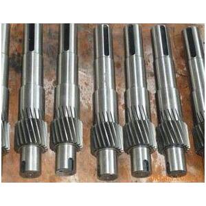
High Precision Customized spur herringbone helical double gears forged shaft
Main Testing and Inspection Device
| No. | Device | Type | Qty | Status | Note |
| 1 | End quenching machine | DZJ-I | 1 | working | Testing |
| 2 | Electric resistance furnace | SX2-8-12 | 2 | working | Testing |
| 3 | Inverted metallurgic microscope | 4XCE | 1 | working | Inspection |
| 4 | High temperature box resistance furnace | SX2-4-13 | 1 | working | Testing |
| 5 | Automatic digital display Rockwell hard-tester | 200HRS-180 | 1 | working | Inspection |
| 6 | Electronic Brinell hardness tester | THB-3000 | 1 | working | Inspection |
| 7 | HR-150B Rockwell hardness tester | HR-150B | 1 | working | Inspection |
| 8 | Rapid multi-element analyzer | JS-DN328 | 1 | working | Inspection |
| 9 | Electric arc furnace | JSDL-8 | 1 | working | Testing |
| 10 | Rapid multi-element analyzer(C & S) | JS-DN328 | 1 | working | Inspection |
| 11 | Infrared thermometer | AR872 | 2 | working | Inspection |
| 12 | Portable chemical composition analyzer | AR872 | 2 | working | Inspection |
| 13 | Test specimen sampler | KW30-6 | 1 | working | Inspection |