
110kw Vertical MCC VSD Control Panel VFD 380V 3 Phase For Pump Control
Brand Name:CHIFON
Certification:CE,ISO,SGS,EAC
Model Number:FPR500A-110G/132P-T4
Minimum Order Quantity:1pcs
Delivery Time:sample order 2 working days, bulk order 7-10 working days
Payment Terms:L/C, T/T, Paypal
Contact Now
Add to Cart
Active Member
Location:
Hangzhou Zhejiang China
Address:
No. 25 Xianxing Rd, Xianlin Industrial Park, Hangzhou, Zhejiang, China
Supplier`s last login times:
within 26 hours
Product Details
Company Profile
Product Details
110kw Vertical MCC Control Panel VFD VSD 380V 3 Phase For Pump Control
What is a VSD/VFD?
A Variable Frequency Drive (VFD) is a type of motor controller that drives an electric motor by varying the frequency and voltage supplied to the electric motor. Other names for a VFD are variable speed drive, adjustable speed drive, adjustable frequency drive, AC drive, microdrive, and inverter.
Frequency (or hertz) is directly related to the motor’s speed (RPMs). In other words, the faster the frequency, the faster the RPMs go. If an application does not require an electric motor to run at full speed, the VFD can be used to ramp down the frequency and voltage to meet the requirements of the electric motor’s load. As the application’s motor speed requirements change, the VFD can simply turn up or down the motor speed to meet the speed requirement.
The first stage of a Variable Frequency AC Drive, or VFD, is the Converter. The converter is comprised of six diodes, which are similar to check valves used in plumbing systems. They allow current to flow in only one direction; the direction shown by the arrow in the diode symbol. For example, whenever A-phase voltage (voltage is similar to pressure in plumbing systems) is more positive than B or C phase voltages, then that diode will open and allow current to flow. When B-phase becomes more positive than A-phase, then the B-phase diode will open and the A-phase diode will close. The same is true for the 3 diodes on the negative side of the bus. Thus, we get six current “pulses” as each diode opens and closes. This is called a “six-pulse VFD”, which is the standard configuration for current Variable Frequency Drives.
We can get rid of the AC ripple on the DC bus by adding a capacitor. A capacitor operates in a similar fashion to a reservoir or accumulator in a plumbing system. This capacitor absorbs the ac ripple and delivers a smooth dc voltage. The AC ripple on the DC bus is typically less than 3 Volts. Thus, the voltage on the DC bus becomes “approximately” 650VDC. The actual voltage will depend on the voltage level of the AC line feeding the drive, the level of voltage unbalance on the power system, the motor load, the impedance of the power system, and any reactors or harmonic filters on the drive.
The diode bridge converter that converts AC-to-DC, is sometimes just referred to as a converter. The converter that converts the dc back to ac is also a converter, but to distinguish it from the diode converter, it is usually referred to as an “inverter”. It has become common in the industry to refer to any DC-to-AC converter as an inverter.
FPR500A Product sepecifications
| Basic Function | Specification | |
| Maximum output frequency | 0~500Hz | |
| Carrier frequency | 0.5kHz~16.0kHz;According to the load characteristics, carrier frequency can be adjusted automatically | |
| Input frequency | Range :47~63Hz | |
| Control mode | V/F Open/closed loop vector control(SVC/FVC) | |
| Speed range | 1:50(Vector mode 0 ) 1Hz/150% rated torque | |
| Overload capability | G type:150% rated current for 60s; 180% rated current for 3s 150% rated current for 3s | |
| Torque boost | Auto Torque boost Manual Torque boost; 0.1%~30.0%. | |
| V/F curve V/F | Four modes : Line , Multi-point , Square V/F curve, V/F separation | |
| Jog control | Jog frequency range:0.00Hz to F0-10(Max frequency) | |
| Accelerate/Decelerate curve | Line or S-curve Acc/Dec mode, four kinds of Acc/Dec time Range of Acc/Dec Time0.0~65000.00s. | |
| DC brake | DC brake frequency: 0.00Hz to Maximum frequency brake time: 0.0 to 36.0s brake current value: 0.0 to 100% | |
| Simple PLC, Multi-speed | 16-speed operating through built-in PLC or control terminal | |
| Built-in PID | Close loop control system can be formed easily by using PID | |
| Automatic voltage regulating (AVR) | Output voltage is regulated when voltage of the power network changes | |
| Overvoltage and over current stall control | During operation automatically limits the inverter output current and bus voltage, to prevent fan over current and overvoltage trip. | |
| Rapid current limiting function | Minimizing flow failures, protect the normal operation of the inverter | |
| Instantaneous stop non-stop | Load feedback energy compensation voltage is reduced and continues to maintain a short time when change is momentarily interrupted. | |
| Speed tracking start | For high-speed rotation of the motor speed identification, impact- free smooth start | |
| Rapid current limit | Rapid software and hardware limiting technology to avoid frequent converter over current fault. | |
| Virtual IO | Five sets of virtual DO, five sets of virtual DI, enables easy logic control. | |
| Timing Control | Timing control: set the time range 0.0Min~6500.0Hour | |
| Multi-motor switch | Two independent motor parameters, enabling two motors switching control | |
| Bus Support | Two independent Modbus communication, CAN-Link | |
| Command source | Given the control panel, control terminal, serial communication
port given. It can be switched by a variety of ways. | |
| Torque boost | Auto Torque boost Manual Torque boost ; 0.1%~30.0%. | |
| Frequency source | Nine kinds of frequency sources: digital setting, analog voltage setting, analog current setting, pulse setting, or serial port and so on. It can be switched by a variety of ways. | |
| Auxiliary frequency source | Nine kinds of auxiliary frequency source. Flexible implementation
of auxiliary frequency tuning, frequency synthesis. | |
| Input terminal | Six digital input terminals, one only supports 50khz high pulse
input Two analog input terminals, one support 0V~10V voltage input One support 0 ~ 10V voltage input or 0 ~ 20mA current input | |
| Output terminal | One high-speed pulse output terminal (optional open collector
type), support of square wave 0 ~ 50kHz signal output One digital output terminal One relay output terminals Two analog output terminals, support 0 ~ 20mA current output or 0 ~ 10V voltage output | |
| Display and operation | ||
| LED display | Display parameters and status information | |
The key lock and function selection | Achieve some or all of the keys locked, scope definition section
keys to prevent misuse. | |
| Protection function | Input/output phase failure protection ,Overcurrent protection ;Over voltage protection; Undervoltage protection; Overheat protection ; Overload protection | |
| Options | Brake assembly, PG card | |
| Environment | ||
| Application environment | In-door, free from direct sunlight, dust , corrosive gas, combustible gas, oil mist , steam , water drop and salt . | |
| Altitude | Lower than 1000m | |
| Vibration | Less than 5.9m/s(0.6g) | |
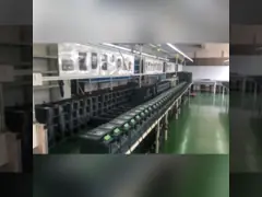
Field Application Photos:
Product packaging:


110kw Vertical MCC VSD Control Panel VFD 380V 3 Phase For Pump Control
Inquiry Cart
0